General Application of Switches
Ratings
The ratings are the values that warranty standards for the characteristics and performance of a switch. This generally indicates the maximum current that can flow through the contacts.
The value of the current depends on the size of the voltage and the type of load.
The maximum current that can flow through the switch contacts for each applied voltage and load is specified.Generally, a large current can flow if the voltage is low.

Load Types & Ratings
Inrush current is a current that is much larger than the steady-state current and that flows as soon as power is input to the electric circuits that operate the load.
Inrush current occurs for loads such as motors and incandescent lamps.
1. Inrush Current
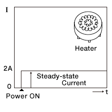
Resistive Loads

The current is constant from the time that power is turned ON.
Lamp Loads

Inrush current of approximately 10 times the steady-state current flows as soon as power is turned ON and then the current becomes constant.
2. Inrush Current and Rating

If ratings are given for both motor loads and lamp loads, switch applicability is determined with the relevant value.
If the rating is given only for a resistive load, the inrush current for the actual load is calculated to determine if the rating would be exceeded.
Examples:
| Heater | → | A resistive load. | The steady-state current must be less than the resistive load rating. |
|---|---|---|---|
| Incandescent lamp | → | A lamp load. | Ten times the steady-state current must be less than the resistive load rating. |
| Motor | → | A motor load. | Six times the steady-state current must be less than the resistive load rating. |
Include the inrush current when you consider ratings.
Switching DC Circuits
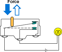
An arc is a spark that occurs between the contacts when the switch turns OFF an electric circuit.
Arcing is more common at higher currents and lasts longer with slower contact switching speeds. If arcing lasts too long, contacts will wear drastically.

Switching DC Circuits
In AC circuits, where the direction of current flow changes, arcing is extinguished every time the voltage goes to 0 V.
With DC circuits, the current always flows in the same direction, which increases arcing time, causes contact wear, and reduces durability.
Contact transfer can also occur, causing rough contact surfaces which can catch and cause failure-to-open malfunctions.

There is also the X Series of Basic Switches for DC currents that provides a magnetic blowout mechanism.
Operating Speeds
Chattering is when the switch repeatedly turns ON and OFF while it is in an ON state because external vibration or other force causes the contacts to open momentarily.
Bouncing is when the switch repeatedly turns ON and OFF because the COM contact bounces due to the shock from switching immediately after the switch operates.
1. Extremely Slow Operating Speeds
The contact between the contacts becomes unstable and chattering occurs.
Incorrect signals are output and arcing causes contact deterioration.

2. Extremely Fast Operating Speeds
The COM contact bounces due to vibration and shock.
Incorrect signals are output and mechanical stress causes damage.

Microloads
A microload is a load that is switched with a circuit current of a few milliamperes.
Microloads are used for signal pulses to input to electronic devices such as those used in microcomputers.
1. Switches for Microloads
For a microload, there is not sufficient energy to destroy the film on the contact surfaces that results from oxidation and sulfurization. This makes contact failure a problem.
We recommend the use of switches for microloads that use contact materials that resist the influence of films (e.g., gold) or that use crossbar contacts, which also resist the influence of films.
They are included in the main models of basic switches.
2. Microload Application
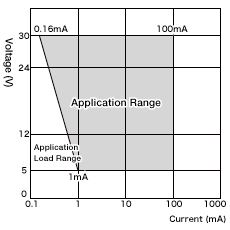
To prevent contact failure, confirm the current-voltage application range that is specified for the switch.

For example,
a switch rated for 0.1 A for 30 VDC with a minimum applicable load of 1 mA at 5 VDC would be used within the trapezoidal area.
The minimum applicable load is the N-level reference value (JIS C5003).This level indicates only one random failure caused by unstable contact resistance for every two million operations.
Install CR circuits or other absorption circuits to prevent noise and incorrect pulses due to bouncing and chattering.
For loads that cause inrush current during switching, insert contact protection circuits because the durability of the switch will be reduced.
Switch Durability
The durability (life) of a switch is the number of switching operations that can be performed by the switch before the specified operating characteristics and performance can no longer be achieved.
There are two types of durability (life): mechanical durability and electrical durability.
1. Mechanical Switch Durability (Life)
This is the durability for operation at the specified frequency and stroke test conditions without supplying power to the switch.

When the contacts are switched, Contact Wear occurs. *1
*1 Contact Wear:
Wear that occurs in contacts.
2. Electrical Switch Durability (Life)
This is the durability for operation at the specified frequency and stroke test conditions with a load connected and the rated current and voltage applied.

When the contacts are switched, Contact Eroslon occurs. *2
*2 Contact Eroslon:
The fusing and spattering of contact material caused by arcing and other factors.
Operating Stroke
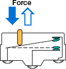
The operating stroke is the movement of the actuator caused by the operating body that is required for the switch to operate correctly.

- The actuator must normally be in the free position(FP).(The operating body is separated from the actuator.)
- The mortion of the operating body must not stop at the operating position (OP) and the reversing position(RP).
- When the operation reverse position(suitable pushing of the actuator) is set, the motion of the operating body must be adjustable based on the specified operating travel(OT) value.
- When the switch is placed in a device, the suitable pushing point of the operating body has to be 60% to 90% in the operating position(OP) to the total travel position (TTP).

Failure
Causes and Countermeasures for Main Switch Failure
| Failure | Assumed cause | Countermeasure | |
|---|---|---|---|
| Failure in electrical characteristics | Contact failure | Foreign matter is attached to the contacts. | Use sealed switches to prevent the entry of foreign matter. |
| Films forming on contact surfaces | Use switches with gold contacts, which have wiping effects. | ||
| Insufficient contact force between the contacts caused by an incorrect stroke. | Set a suitable stroke. | ||
| Malfunction | Contact chattering caused by vibration or shock. | Use switches with large contact forces between the contacts (i.e., with a high operating force (OF)). | |
| Welding | The switching capacity of the contacts was exceeded. | Use a high-capacity switch. Insert a contact protection circuit. | |
| Insulation deterioration | The contacts are spattering due to arcing. | Use a high-capacity switch. | |
| Failure in mechanical characteristics | Failure to operate | The mechanism is damaged due to an incorrect stroke, overload, or shock. | Set a suitable stroke and operate the switch at a suitable operating speed and with a suitable load. |
| Foreign matter has entered the switch and is caught in the mechanism or contacts. | Use sealed switches to prevent the entry of foreign matter. | ||
| External damage | An overload was placed on the actuator because of the dog or cam shape or because an unsuitable operating method was used. | Change the design of the dog or cam and use suitable operating methods. | |

