- MOS FET Relay
- Mechanical Relay
vs.
MOS FET Relay - Semiconductor Device vs.
MOS FET Relay - MOS FET Relay
Lineup
Semiconductor relay that combines LEDs and
MOS FET chips to realize relay functions
A MOS FET relay is a non-contact relay used primarily for switching and connecting signals. It has mechanical relays and semiconductors features and is used in a semiconductor inspection system, various measurement devices, security equipment, and a wide range of other applications.
![[MOS FET relay]Mechanical Relay (Reed Relay), Low ON Resistance, Versatility, High Isolation, Excellent Linearity, Long Life, Compact, Low Noise, Semiconductor Device](/us-en/sites/components.omron.com.us/files/2022-10/mos_fet_01_02_2_en.png)
![[Photocoupler]A photocoupler is a component consisting of a light emitting diode (LED) and a light receiving element. The input electrical signal is converted into an optical signal by the LED, and the light-receiving element converts the optical signal into an electrical signal again to output it. It is mainly used when electrical isolation between the input and output circuits is required in order to reduce noise effects and safety risks. There are three major types of photocouplers, and the primary difference is the type of light-receiving element used. A MOS FET relay is also a type of photocoupler. [Transistor coupler]Light-receiving element, Phototransistor[TRIAC coupler]Light-receiving element, Photo TRIAC [MOS FET relay]Light-receiving element, PDA + MOSFET](/us-en/sites/components.omron.com.us/files/2022-10/mos_fet_01_03_en.png)
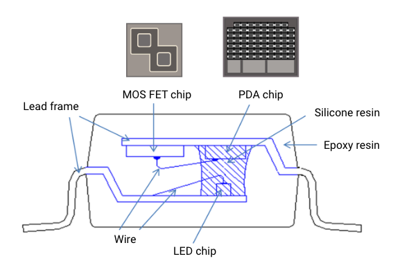
MOS FET Relay Cross Section
A MOS FET relay is a semiconductor relay that uses MOS FET as its output element.
The MOS FET relay consists of the following three chips:
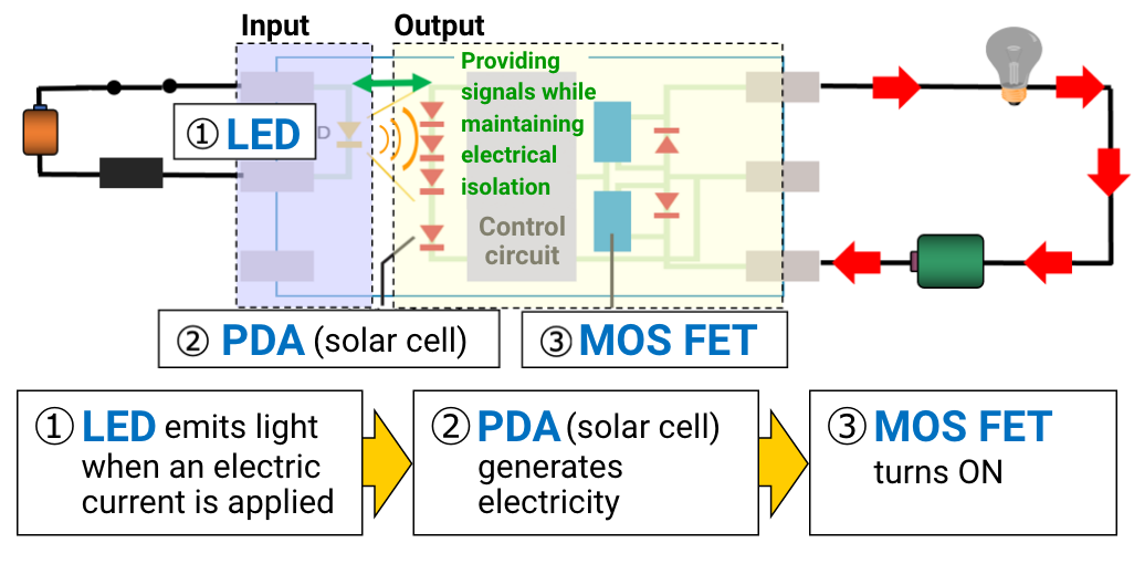
Principle and Function of MOS FET Relay
Compared with mounting area for 10 pieces (mounted at 0.3mm intervals)
![(General reed relay)Size: 20mm x 5mm x 5mm, Mounting area: 20mm x (5+0.3) x 10 = 1060mm2(G3VM S-VSON package)Size: 2mm x 1.45mm x 1.65mm, Mounting area: 2mm x (1.45+0.3) x 10 = 35mm2[Mounting area can be reduced by about 65%]](/us-en/sites/components.omron.com.us/files/2022-10/mos_fet_02_03_2_en.png)
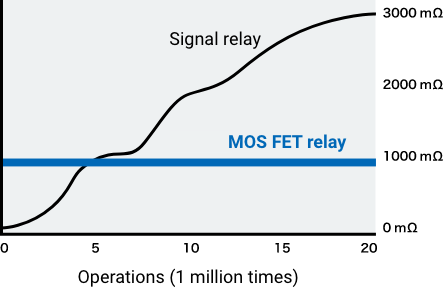
![Mechanical relay, Reed relay, MOS FET relay[No switching life]](/us-en/sites/components.omron.com.us/files/2022-10/mos_fet_02_05_en.png)
Since there are no contacts (i.e., no mechanical life), it contributes to reducing maintenance frequency in equipment that uses many relays.
Compared to mechanical relays, the ON resistance of MOS FET relays that have no contacts does not depend on the number of switching cycles.
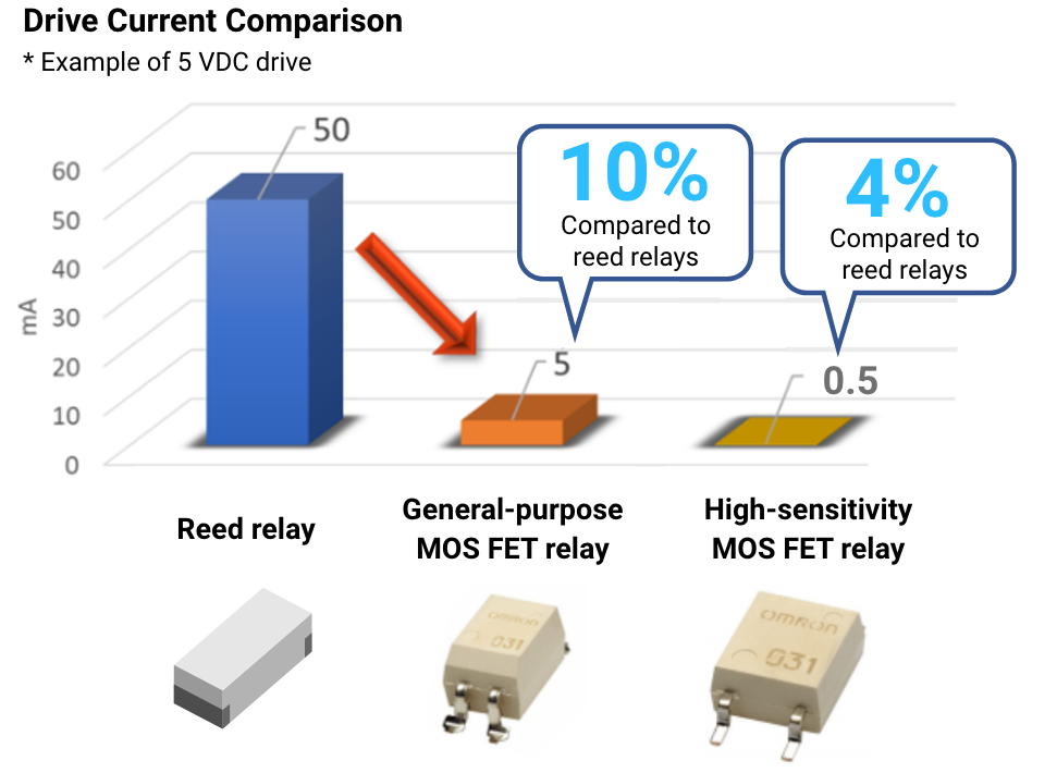
Compared to reed relays, power consumption on the input is very low, contributing to the energy saving of equipment.
| Mechanical Relay (Reed Relay) |
VS | MOS FET Relay |
|---|---|---|
 |
 |
 No mechanical contact No mechanical contact= No contact sound |
 |
 |
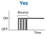
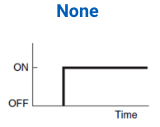 No mechanical contact No mechanical contact= No contact bouncing |
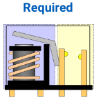 Surge absorber is required to protect peripheral circuits from surges (reverse voltage) generated by the coil Surge absorber is required to protect peripheral circuits from surges (reverse voltage) generated by the coil |
 |
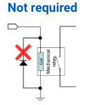 No coil, thus no surge No coil, thus no surge(reverse voltage) |
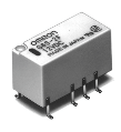 G6S-2F G6S-2F220 VDC |
 |
High-voltage type comparable to mechanical relays also available G3VM-601DY1 G3VM-601DY1Max. 600 VDC |
 G6S-2F G6S-2F2000 VAC (1 min.) |
 |
High-dielectric strength type comparable to mechanical relays also available G3VM-601DY1 G3VM-601DY1Max. 5000 VAC (1 min.) |
The output elements of transistor couplers and TRIAC couplers have low linearity, resulting in distortion of the signal passing between outputs.
Unlike transistor couplers and TRIAC couplers, MOS FET relays suppress signal distortion due to their excellent linearity characteristics comparable to mechanical relays.
The ability to control analog signals makes it ideal for testers and measuring instruments.
![[Load current vs. Load voltage]](/us-en/sites/components.omron.com.us/files/2022-10/mos_fet_03_03_en.png)
![[Signal transfer]](/us-en/sites/components.omron.com.us/files/2022-10/mos_fet_03_04_en.png)

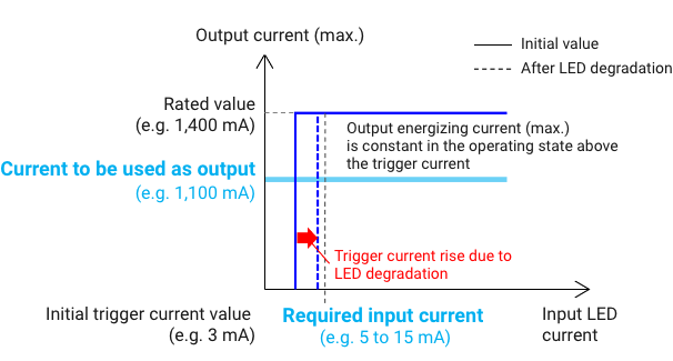
The output switching current of MOS FET relays is not affected by the input current.
MOS FET relays can operate at very low currents, contributing to power savings in equipment. Even after its lifetime, the output current does not drop as it does with transistor couplers.

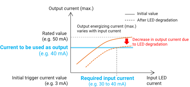
Transistor couplers consume more power than MOS FET relays because a larger input current also results in a larger output current.
Therefore, more power is consumed because the output is also weakened by LED degradation.
| Transistor coupler | G3VM-61CR1 (MOS FET relay) |
|
|---|---|---|
| LED input current | 1 to 10 mA | 5 mA |
| Output switching current | 1 to 20 mA | Max. 10,000 mA Connection C |
Compared to other semiconductor devices, the leakage current in the off-state is very small, making it possible to measure minute currents. Suppressing unnecessary leakage current contributes to lower heat generation and less circuit malfunctions, which are factors in performance degradation.
| Transistor coupler | TRIAC coupler | G3VM-41GR8 (MOS FET relay) |
|
|---|---|---|---|
| Leakage current | Approx. 10 uA | Approx. 100 nA | Max. 1 nA |
Variations available for both AC and DC expand the range of applications.
| Transistor coupler | TRIAC coupler | MOS FET relay |
|---|---|---|
DC only |
AC only |
Supporting AC or DC |
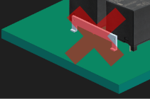
Low heat generation due to low on-resistance
No heat sinks or other components to dissipate heat are required.
Package Types

MOS FET Relay Model Standard

MOS FET Relay Packaging Types

Product Map
OMRON offers a wide range of MOS FET relays so that you can select the right product for your application.
For a selection of MOS FET relays, please refer to the product selection guideline.
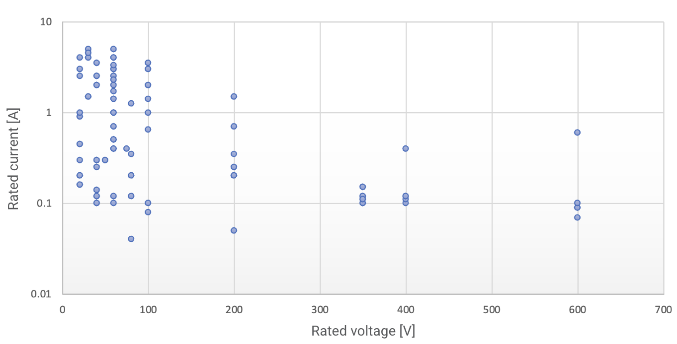
Product Selection Guideline
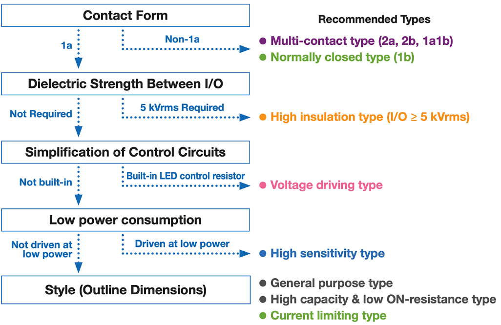
| Multi-contact type | Click here to see our recommended lineup |
| Normally closed type | Click here to see our recommended lineup |
| High insulation type | Click here to see our recommended lineup |
| Voltage driving type | Click here to see our recommended lineup |
| High sensitivity type | Click here to see our recommended lineup |
| General purpose type | Click here to see our recommended lineup |
| High capacity & low ON-resistance type | Click here to see our recommended lineup |
| Current limiting type | Click here to see our recommended lineup |


