What are the basics of an electrical relay?
- Basics
- Technology
- Applications
- Standards
- Glossary
Electrical Relay Definition
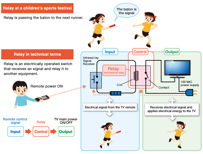
Relays are electrically operated switches that open and close the circuits by receiving electrical signals from outside sources. Some people may associate “relay” with a racing competition where members of the team take turns passing batons to complete the race.
The “relays” embedded in electrical products work in a similar way; they receive an electrical signal and send the signal to other equipment by turning the switch on and off.
For example, when you push the button on a TV remote to watch TV, it sends an electrical signal to the “relay” inside the TV, turning the main power ON. There are various types of relays used in many applications to control different amounts of currents and number of circuits.
Electrical Relay Types and Classification
Relay technology can be divided into two main categories: Movable contacts (mechanical relay) and no movable contacts (MOS FET relay, solid state relay).
Movable contacts
( Mechanical Relay )

This type of relay has contacts that are mechanically actuated to open/close by a magnetic force to switch signals, currents and voltages ON or OFF.
No movable contacts
( MOS FET relay, Solid State Relay )

Unlike mechanical relays, this type of relay has no moving contacts but instead employs semiconductor and electrical switching elements such as triac and MOS FET. By the operation of these electronic circuits, signals, currents and voltages are switched ON or OFF electronically.
Electrical relay Structure and Operating Principles
1. Mechanical Relay
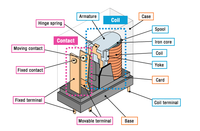
Basic structure of mechanical relays
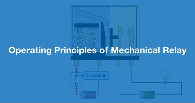
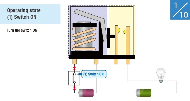
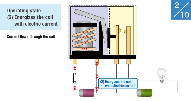
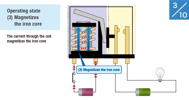
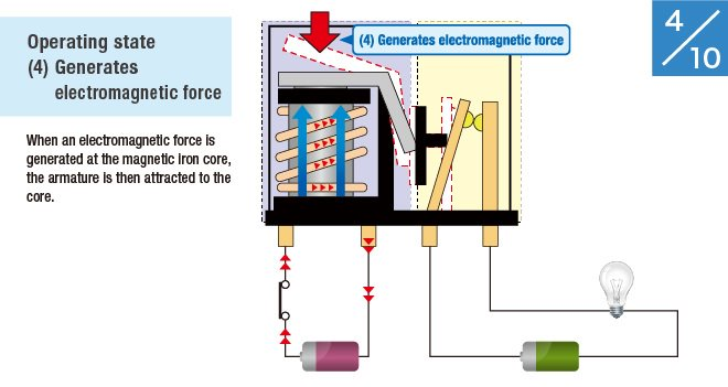
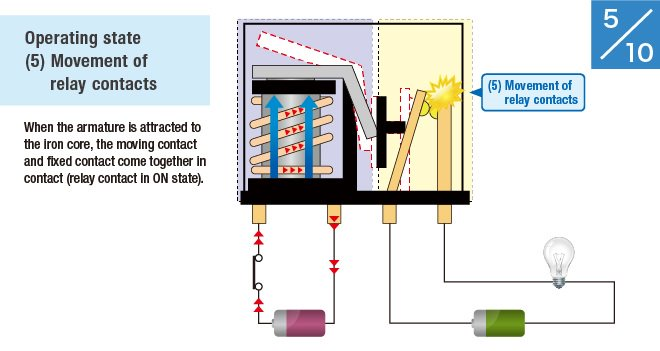
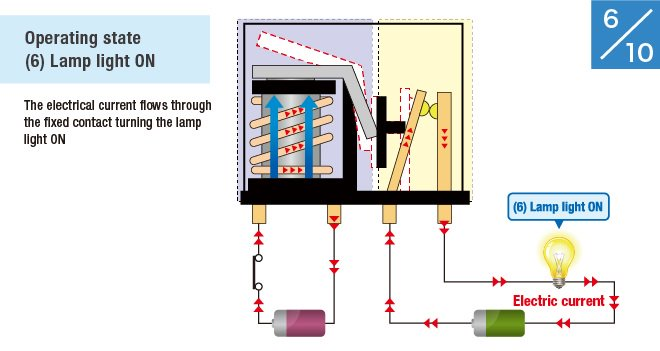
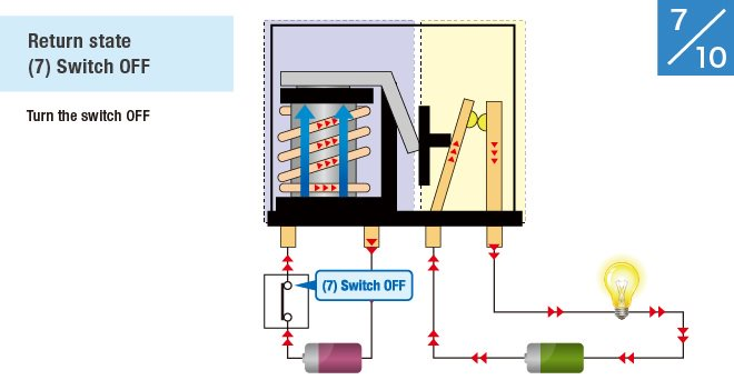
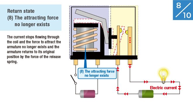
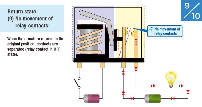
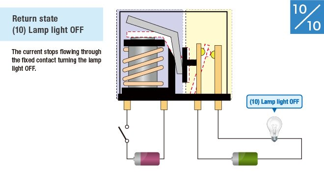
Relay consists of a coil, which receives an electric signal and converts it to a mechanical action and contacts that open and close the electric circuit.
Operating principles of mechanical relays
Let's take a closer look at how a lamp is turned on using a switch and a relay.
To go to the next slide.
2. MOS FET Relay
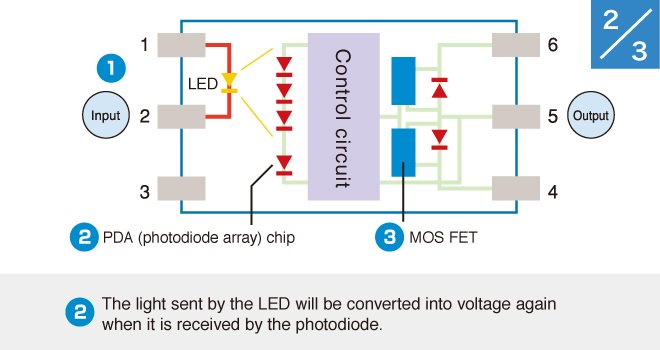
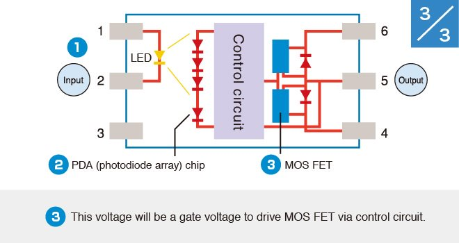
Basic structure of MOS FET relays
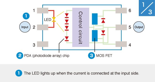
MOS FET relay is a semiconductor relay that uses power MOS FETs in output elements.
MOS FET relay consists of the following three components:
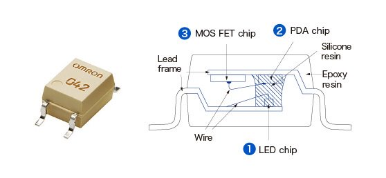
LED ( light-emitting diode ) chip
PDA ( photodiode array ) chip
*Photodiode Array ( solar cell + control circuit )
MOS FET chip
*Metal Oxide Semiconductor Field Effect Transistor ( metal, oxide, semiconductor, field, effect, transistor )
Operating principles of MOS FET relays
MOS FET relays operate according to the following principles.
To go to the next slide.
Electrical relay Characteristics and Mechanism
1. Characteristics of Electrical Relay
Mechanical Relay
One of the major characteristics of a mechanical relay is the physical spacing between the coil and the contact component in order to achieve appropriate level of insulation (insulation distance) on both input and output.
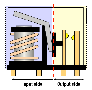
Coil
The electromagnet attracts the armature.
Contact
The combination of fixed and movable contacts opens and closes the control circuit.
MOS FET Relay
One of the major characteristics of a MOS FET relay is that it utilizes semiconductor so the contacts do not mechanically open/close. As a result, benefits include reduction of footprint, quiet operation, longer operating life, and eliminating the need for additional maintenance.
| Ultra small and weight | In addition to SSOP and USOP, our new ultra-compact VSON package size offers substantial space-saving of the entire system. |
| Low driving current | The standard driving current should be 2-15 mA. Ultrasensitive models are also available featuring drive currents as low as 0.2 mA(max), allowing it to conserve energy of the entire system. |
| Longer operating life | The structure uses light signal hence no contacts; avoids reduction of life caused by contact wear and extends its operating life. |
| Small leakage current | MOS FET relay can withstand external surge current without addition of snubber circuit. Under normal condition, leakage current is about 1 nA or below and very small leakage when closed. (Model: G3VM-□GR□, -□LR□, -□PR□, -□UR□) |
| Excellent shock resistance | All the internal parts use casting method and no movable parts are used; increases resistance to shocks and vibrations. |
| Silent operation | Unlike an electromechanical relay, MOS FET relay does not use mechanical contacts; hence, no switching noise, contributing to silent system operation. |
| High insulation | Allows electric I/O isolation by converting voltage signal into light signal for transmission. The standard models offer withstanding voltage of 2,500 VAC between the input and output. Superior products offering 5000 VAC are also available, achieving high insultation level. |
| High-speed switching | Achieves 0.2 ms (SSOP, USOP, VSON) of switching time; much faster speed compared with the mechanical relay (3 to 5 ms), achieveing quick response performance. |
| Accurate control of the micro analog signal | Compared to the triac, MOS FET significantly reduces the dead zone, allowing very little occurrence of input waveform distortion of the micro analog signal to correctly convert into output waveform. |
2. The Three Actions of Electrical Relays
1. The relay permits a small amount of electrical current to control high current loads.
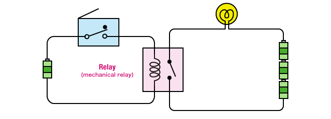
When voltage is supplied to the coil, small current passes through the coil, resulting in a larger amount of current passing through the contacts to control the electrical load.
2. The relay sends different types of electrical signals.
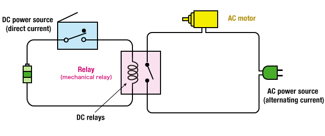
AC loads can also be electrically controlled (Switching) from DC power source.
3. The relay drives multiple outputs with only one input .
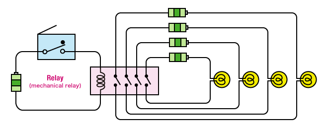
One input signal to the coil can simultaneously control several independent circuits (switched).
- Basics
- Technology
- Applications
- Standards
- Glossary

