Photomicrosensor Basics: Design Ⅱ
(Design of Systems Incorporating Photomicrosensors)
(2) Photo IC Output
Circuit Configuration
The following explains the circuit design method for the Photomicrosensors (photointerrupters) with Photo IC output. Figure 19 shows the internal circuit configuration of EE-SX3081 (Dark-ON output) / EE-SX4081(Light-ON output); two of our typical models.
Figure 19. Circuit Configuration
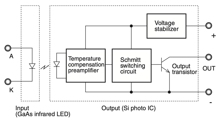
LED Forward Current (IF) Supply Circuit
The LED in the above circuitry is an independent component, to which an appropriate current must be supplied from an external power supply. This is the most important item required by the photo IC type Photomicrosensor (photointerrupter).
It is necessary to determine the appropriate LED forward current (IF) that turns the photo IC ON. If the appropriate IF is determined, then the Photomicrosensor can be easily used by simply supplying power to the output side circuitry (i.e., the photo IC).
Refer to the datasheet of the Photomicrosensor to find the current of the LED turning the photo IC ON. Table 4 is an extract of the datasheet of the EE-SX3081(Light-OFF output) / EE-SX4081(Light-ON output).
Table 4. Abstract of Characteristics EE-SX3081/EE-SX4081
| Item | Symbol | Value | Unit | Condition | ||
|---|---|---|---|---|---|---|
| MIN. | TYP. | MAX. | ||||
| LED current when output is turned OFF (EE-SX301) | IFT | - | - | 8 | mA | VCC = 4.5 to 16 V |
| LED current when output is turned ON (EE-SX401) | ||||||
To design systems incorporating EE-SX3081 or EE-SX4081, the following are important points.
The IFTOFF value of the EE-SX3081 (the IFTON value of the EE-SX4081) is specified as 8 mA maximum according to the datasheet. Then the LED forward current (IF) for EE-SX3081 and EE-SX4081 must be 8 mA or more in actual operation.
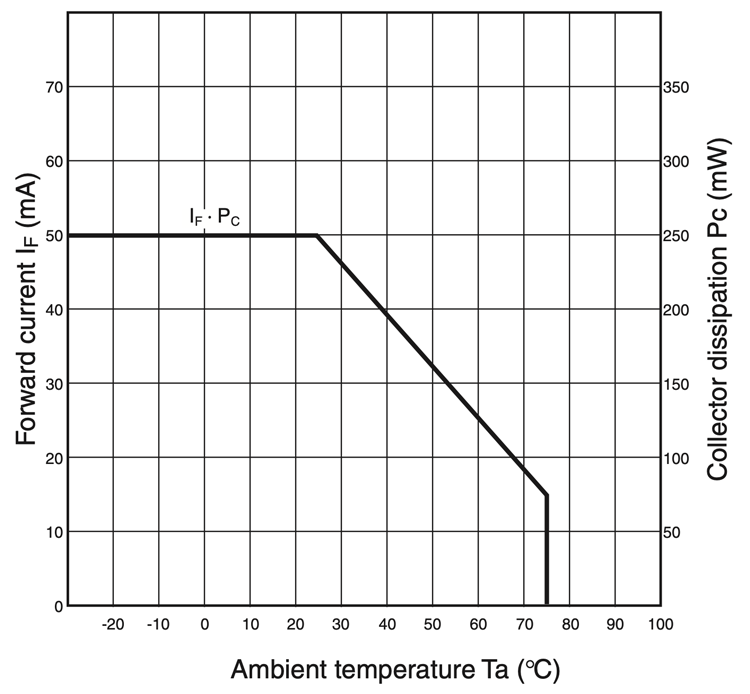
The upper limit of the IF for EESX3081 / 4081 is specified in the absolute maximum ratings of the datasheet, which are shown in Figure 20. The actual IF should be designed as large as possible within the temperature rating line in the graph. The IF value must not be close to 8 mA, otherwise the photo IC of the EESX3081 / 4081 may not operate if there is any ambient temperature change, aging change of the LED, or dust sticking to the LED. The IF values in actual operation is recommended to be twice as large as the IFTOFF (the IFTON ) values of the EE-SX3081(EE-SX4081).
Figure 20. Forward Current vs.
Temperature Ratings
EE-SX3081 / 4081
Absolute Maximum Ratings (Ta = 25ºC)
EE-SX3081 / 4081
| Item | Symbol | Rated value | Unit | |
|---|---|---|---|---|
| Emitter | Forward current | IF | 50*1 | mA |
| Reverse voltage | VR | 4 | V | |
| Detector | Power supply voltage | VCC | 16 | V |
| Output voltage | VOUT | 28 | V | |
| Output current | IOUT | 16 | mA | |
| Permissible output dissipation | Popr | 250*1 | mW | |
| Operating temperature | Topr | -40 to 75 | °C | |
| Storage temperature | Tstg | -40 to 85 | °C | |
| Soldering temperature | Tsol | 260*2 | °C | |
*1. Refer to the temperature rating chart if the ambient temperature exceeds 25°C.
*2. Complete soldering within 10 seconds.
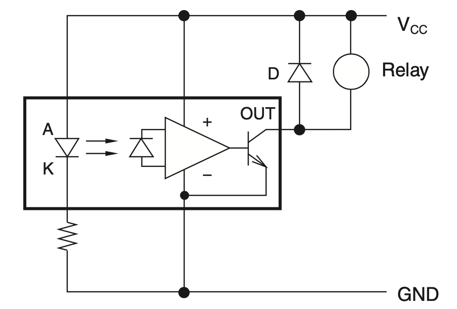
Figure 21 shows the basic circuit of a typical photo IC type Photomicrosensor (photointerrupter). If the photo IC type Photomicrosensor is used to drive a relay, be sure to connect a reverse voltage absorption diode (D) to the relay in parallel as shown in Figure 21.
Figure 21. Basic Circuit
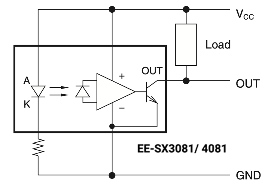
Figure 22. Connected to Inductive load
Output (Detector) Side Circuit
Supply a voltage within the absolute maximum ratings to the positive and negative terminals of the photo IC shown in Figure 19 and obtain a current within the rated value of IOUT of the output transistor incorporated by the photo IC.
Click here for the photomicrosensor product lineup