Do you have any of the following concerns?


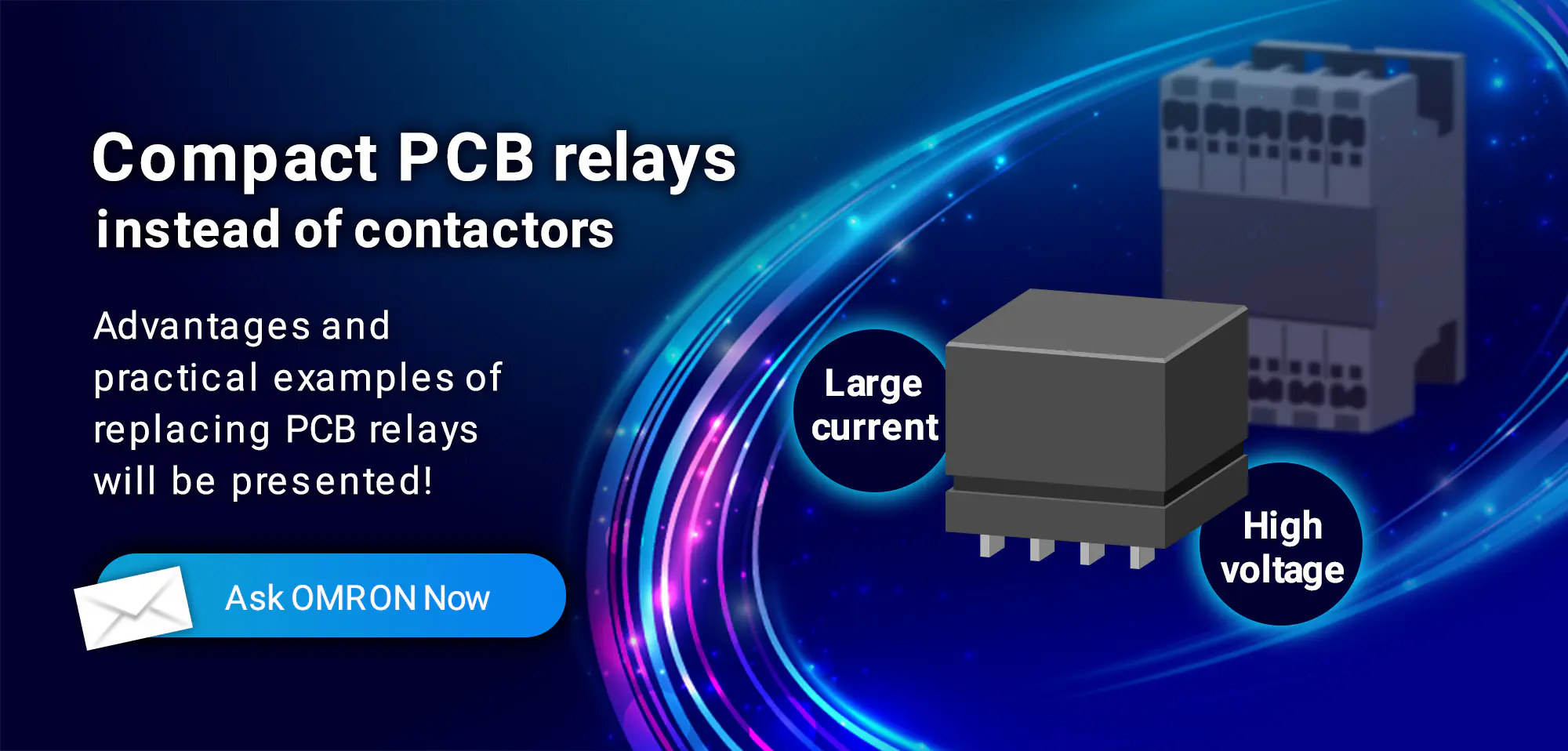
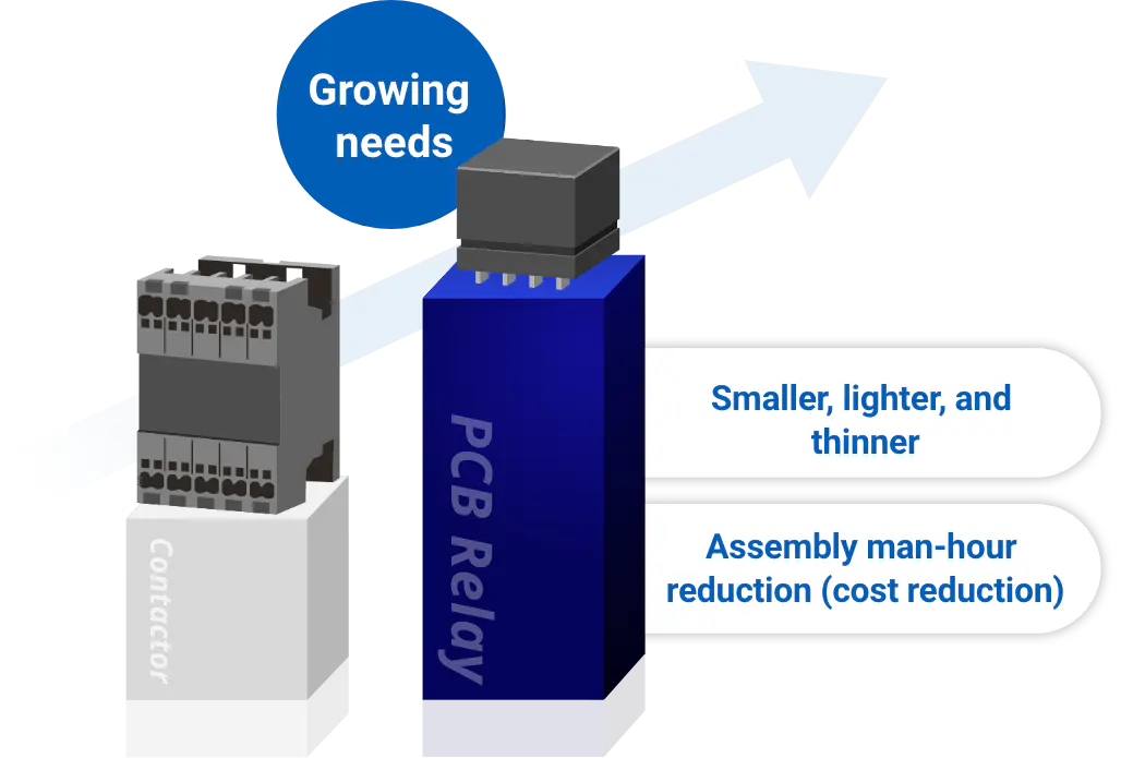
As customers’ products become higher capacity, contactors, which are suitable for controlling large power, are utilized as load switching devices for various electrical equipment requiring large current and high voltage. With the growing need for smaller, lighter and thinner equipment, however, there is an increasing trend to consider replacing large-sized contactors with PCB relays (printed circuit board relays) that are smaller in size and have higher capacity to interrupt large currents and voltages.
In addition, some of our customers are also reducing costs by using PCB relays to integrate load switching devices into a board as one way to reduce man-hours during production, in anticipation of a future surge in demand and expansion of production volume.
As the replacement of contactors with PCB relays progresses in this way, customers may face psychological hurdles to replacement because of the significant design change from conventional cabling and wiring to “integration into PCB”.
In this article, we will introduce various replacement advantages, points to note, actual replacement examples, and our approach to what are the key points for designing PCB relay mounting boards?, which can be provided only because OMRON owns both contactors and high-capacity PCB relays.
Contents
- Evolution of PCB relays and increasing capacity
- Example of Replacing Contactors with High-Capacity PCB Relays
- Difference between contactors and PCB relays
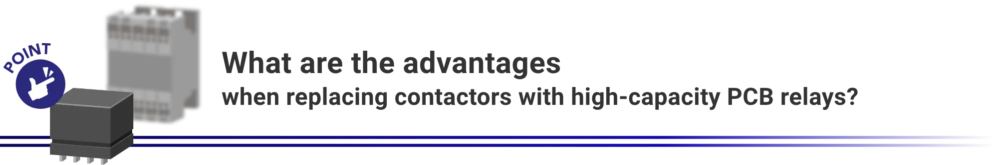
- What are the advantages when replacing contactors with high-capacity PCB relays?
- What should you be aware of when replacing contactors with high-capacity PCB relays?
- What are the key points for designing PCB relay mounting boards?
- OMRON’s high capacity PCB power relay lineup
Evolution of PCB relays and increasing capacity
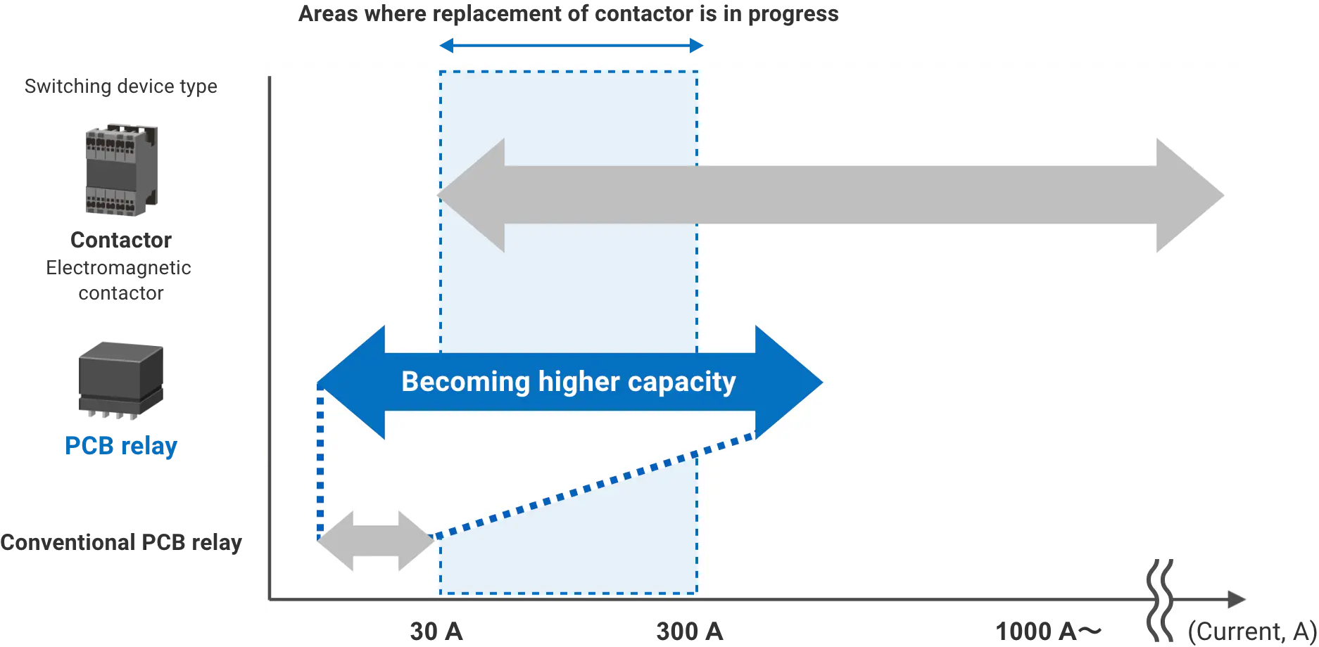
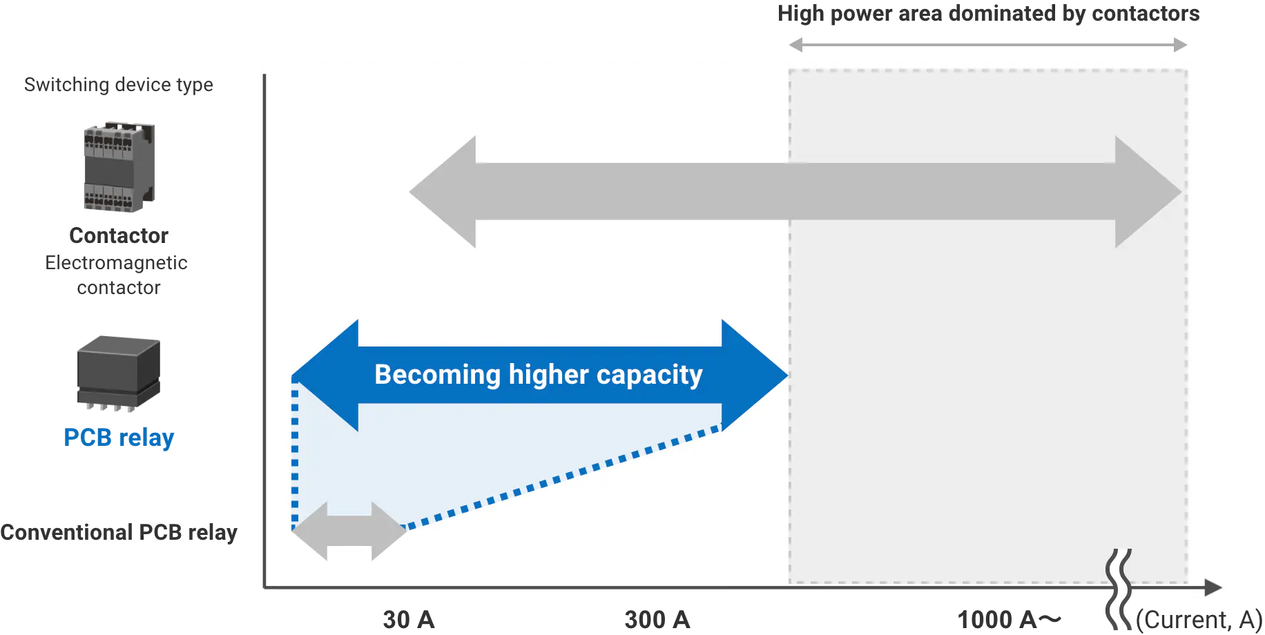
In the past, contactors have been utilized to control large currents, such as those exceeding 30 A, while PCB relays have been utilized to control currents below 30 A. With advances in technology, however, thick copper substrates capable of withstanding large currents and compact PCB relays (PCB relays) capable of turning on and off large currents and voltages are appearing one after another.
As a result, some of the area bands that were conventionally controlled by contactors can now also be controlled by PCB relays. For example, OMRON’s PCB relays can cover current and voltage ranges up to 1000 VAC/VDC and 300 A.
Example of Replacing Contactors with High-Capacity PCB Relays

Replacement study example (1): Circuit-boarding realizes low-profile design

Designer
EMS Division, DAIHEN Corporation
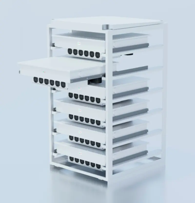
In developing the industry's first unit-type power conditioner (170 kW) compatible with high voltage (1500 VDC), which was released in 2024, the challenges I faced were to make the equipment smaller and to increase the voltage.
In order to reduce the size of the equipment, I proceeded with replacing large contactors with PCB relays. In my search for PCB relays with 1000 VAC withstand voltage and high capacity to achieve higher voltages, I consulted with OMRON, who at the time had the only PCB relay lineup in the relevant capacity range.
Although I had the idea of making a circuit board, I often struggled as it was my first attempt.
However, OMRON not only provided me with suggestions regarding relays, but also introduced me to a circuit board manufacturer and provided me with a lot of support in terms of circuit board mounting design, which enabled me to successfully reduce the size and increase the voltage of the power conditioner. I am particularly impressed with the effect of the replacement of contactors with PCB relays, which has reduced the height of the equipment to less than half.
Our development of the unit-type power conditioner makes it possible to continue operation by isolating only the faulty parts, thereby reducing downtime on site. Furthermore, by changing the number of units, the conditioner can also be used for private consumption in factories, allowing us to broaden the scope of our proposals.
Having heard that OMRON will continue to expand its lineup of large-current, high-voltage PCB relays, I have high expectations for OMRON and look forward to their continued cooperation.
DAIHEN's unit-type power conditioner
DAIHEN's unit section
DAIHEN's unit-type power conditioner
(Overhead view from above)
Replacement study example (2): Circuit-boarding halves the number of man-hours required to assemble a single unit!

OMRON salesperson (Japan)
As a cost reduction measure, there are an increasing number of cases where the replacement of contactors with PCB relays is being considered in fast chargers.
For systems that require multiple units to be controlled, the number of contactors used will increase, and in some cases more than 100 contactors may be required on a single quick charger.
In such cases, assembly requires a lot of man-hours and manpower, including contactor screw installation, busbar screw installation, crimp terminal press-fitting and wiring, and finally, inspection of each individual item, resulting in the assembly of a single quick charger requiring many hours of work.
However, I have heard from our customers that the man-hours required for cable wiring, screw tightening, etc. can be reduced by half by making a circuit board and replacing contactors with PCB relays.
Since the replacement is also expected to have the effect of reducing material costs, I would like to proactively propose the replacement.
Replacement study example (3): Circuit-boarding is being adopted in Europe ahead of other regions
OMRON salesperson (Europe)
In Europe, the trend of developing PCB based instead of panel and DIN rail mounting solutions is already well established avoiding manual mounting and wiring labor costs. Designers have shared their frustration when attempting to value engineer or develop new Inverter related products that needs further space and energy saving.
PCB lends itself especially well to achieving design flexibility. It also affords more opportunity to make reduction to heat dissipation which in turn can result in indirect cost savings and extended electrical life. I’ve helped customers achieve improved solutions in Solar PV Inverters, wall and pedestal mounted EV Chargers, Energy Storage Systems and UPS and more recently in building and factory automation where I’m actively proposing our relays.
Difference between contactors and PCB relays
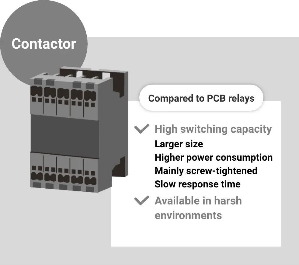
What is a contactor?
Contactors are applied to large installations, e.g., starters for electric vehicles, large lighting control systems. They are also called electromagnetic contactors. Compared to relays, they are designed to control higher currents and voltages and are more robust. As a result, they tend to be larger in physical size and weight than relays, and their switching speeds tend to be relatively slow. In addition, since the electromagnetic coil is large in proportion to the open/close capacity, power consumption tends to be large. The most common installation method is screw-tightening.
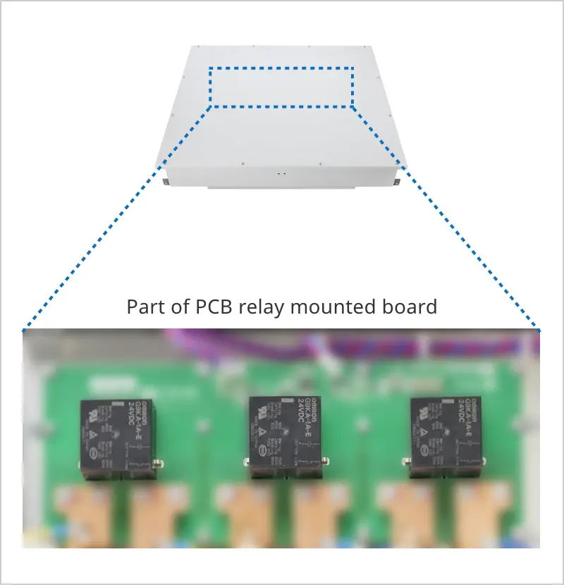
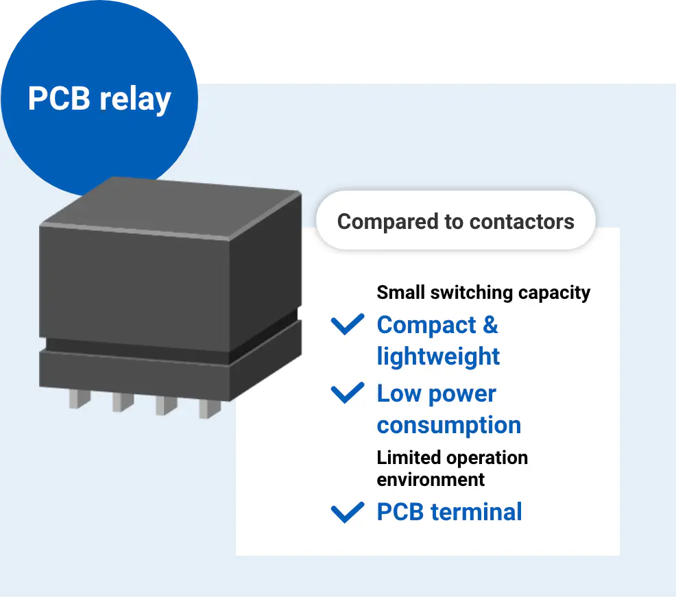
What is a PCB relay?
In general, PCB relays are applied to smaller capacity equipment compared to contactors. Although less robust than contactors, they are now possible to energize, open, and close even loads as large as 300 A by optimizing the magnetic flux design, contact point shape, and arc interrupting path, and utilizing CAE analysis. Compared to contactors, they are smaller, lighter, and can be driven with lower power consumption. The terminal shape is designed to match the board and peripheral components (e.g., terminal block) for printed circuit board terminals (PCB terminals).
(Example of our products: G9KA, G9KB, G9KC)

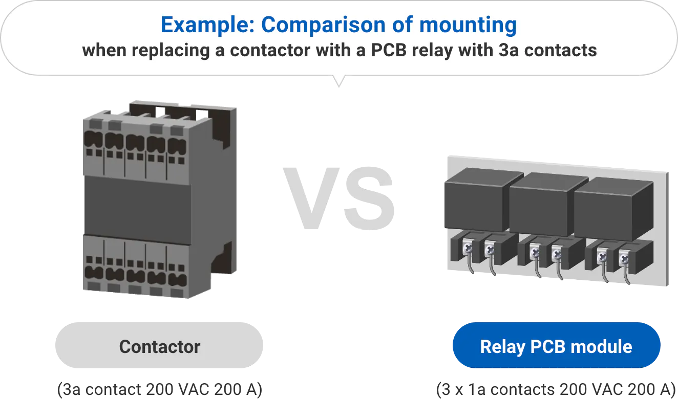
Realization of space-saving design
The major advantage of high-capacity PCB relays is that they are mounted directly on the PCB, making them more compact than contactors when wiring space is factored in. For example, in energy-related equipment, space-saving component mounting can reduce overall equipment size and simplify wiring. They also contribute to effective use of limited installation space.
| Height | Approx. 140 mm |
55 mm 
|
|---|---|---|
| Volume | 2,940,000 mm3 |
425,000 mm3 
|
| Weight | Approx. 2.5 kg/pc |
Total of 0.7 kg/3 pcs 
|
Note: Comparison between a typical contactor in the 200 A band and the relay board module we assume (based on our own research, January 2025).

Cost reduction and higher mass production efficiency
Contactors, which are mostly screw-mounted, are difficult to automate mounting and wiring, and manual work is time-consuming and costly.
In contrast, relays for printed circuit boards (PCB relays) can be easily installed with automated equipment such as pick-and-place machines and flow soldering machines. Therefore, they are easy to integrate into automated manufacturing processes and can significantly reduce manufacturing costs as production volumes increase.
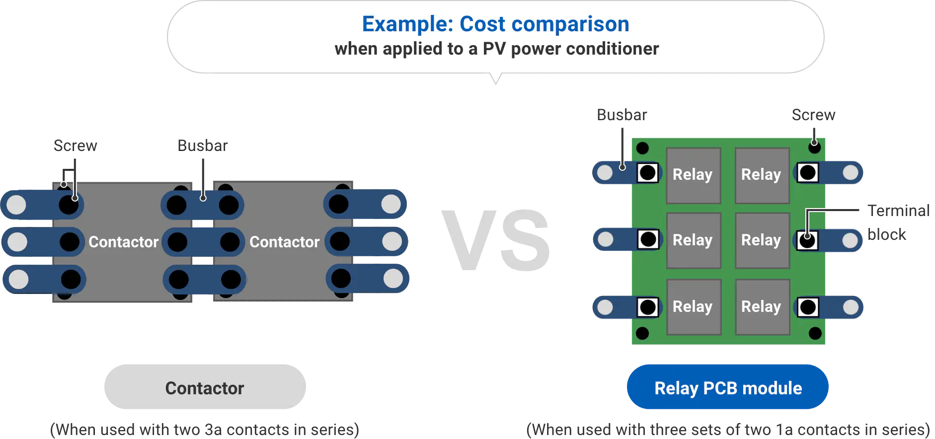
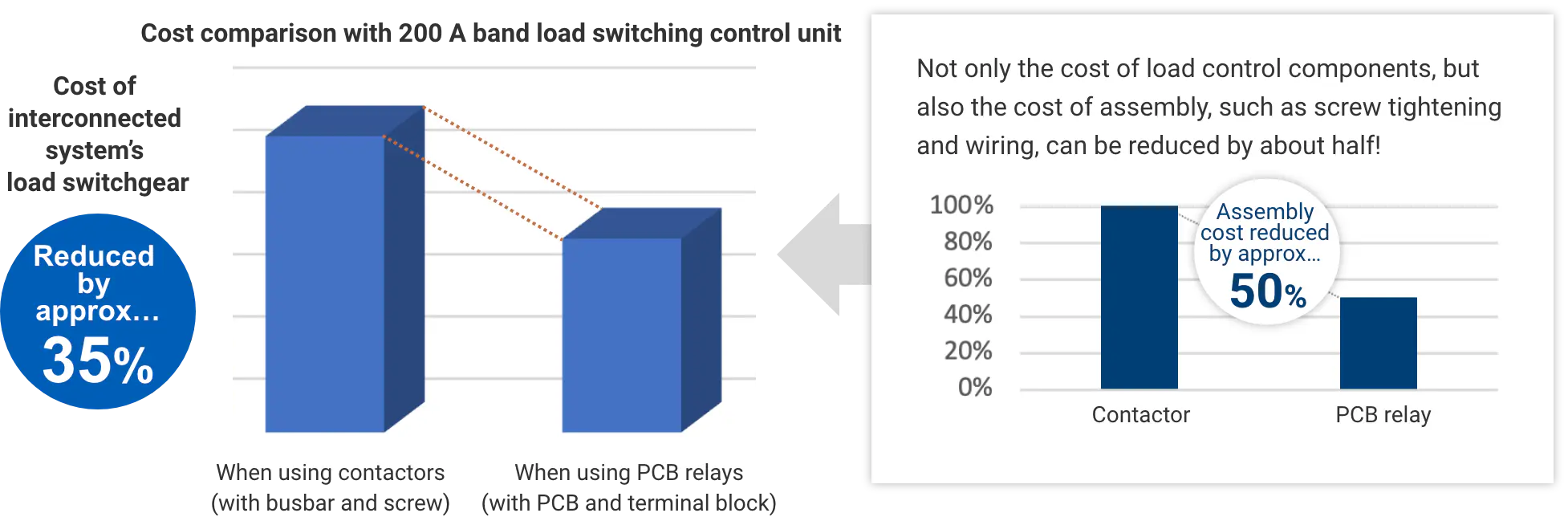
* Cost comparison of a control unit when replacing 2 contactors (3a, 200 A) x 2 with 6 relays (1a, 200 A). Our simulation results (as of January 2025)
These are simulation results under specific conditions and effectiveness is not guaranteed.

Safety features equivalent to contactors
Many high-capacity PCB relays have the weld detection function (optional auxiliary contact with mirror contact structure conforming to IEC60947-4-1) required of contactors and improved insulation resistance. As with contactors, they contribute to a high level of safety.
There are also models with high short-circuit current withstanding capacity in compliance with IEC62955, the standard for EV chargers, and models that guarantee insulation performance with a contact gap of 3.6 mm or more in compliance with VDE0126, the solar power generation standard.
As some of these products ensure reliability in short-circuit and high-voltage environments, they can be reliably used in energy-related equipment.
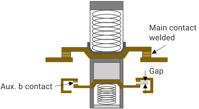
In a combination of a relay body and an auxiliary contact block, if the a-contact (main contact) of the relay body is welded, all b-contacts of the auxiliary contact block are ensured a minimum withstand voltage of 2.5 kV or a minimum contact gap of 0.5 mm even after the coil is de-excited.
Image of mirror contact structure

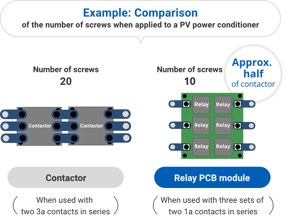
Improved connection reliability
Since contactors are manually screw-tightened, although the fastening torque, such as the screw tightening method and tightening strength, is determined, there are cases where variations in fastening force are inevitably caused by different workers. By using PCB relays instead of contactors, the number of screws can be greatly reduced, contributing to improved connection reliability.
What should you be aware of when replacing contactors with high-capacity PCB relays?

Limitation of maximum current and voltage capacity
Nowadays, PCB relays are becoming high-capacity and replacing contactors in the mainstream high-power area at an alarming rate. However, the maximum current that PCB relays can hold is lower than that of contactors in the high capacitance range, due to the copper foil thickness of the board and the limitation of the current value that can flow on the board. (In the case of our relays, they are currently capable of handling up to 1000 VAC/VDC and 300 A level loads as of October 2024). Contactors may be better suited for applications that control very large currents, such as large industrial equipment or three-phase motors, necessitating selection based on load requirements.
We are adding PCB relays that can control even higher current and voltage loads to our lineup.


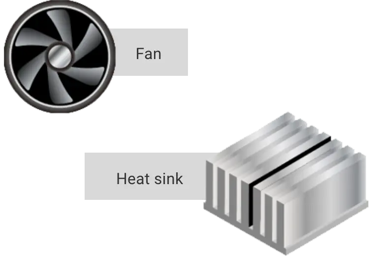
Additional heat-dissipating structure
A barrier to downsizing and higher capacity is the heat generated in the equipment. For example, if the current-carrying capacity of a PCB relay is doubled due to higher capacitance, the amount of heat generated will quadruple. If the temperature becomes too high, however, the board will be damaged. Therefore, PCB relays that carry large currents in the 200 - 300 A class require heat dissipation structures such as fans and heat sinks on the board in some cases. Please consider appropriate cooling and heat dissipation measures as needed.
OMRON also offers a lineup of high-capacity PCB relays with low contact resistance (e.g., initially 0.2 mΩ or less in G9KA), contributing to smaller and thinner devices by reducing heat generation inside devices and heat dissipation mechanisms.

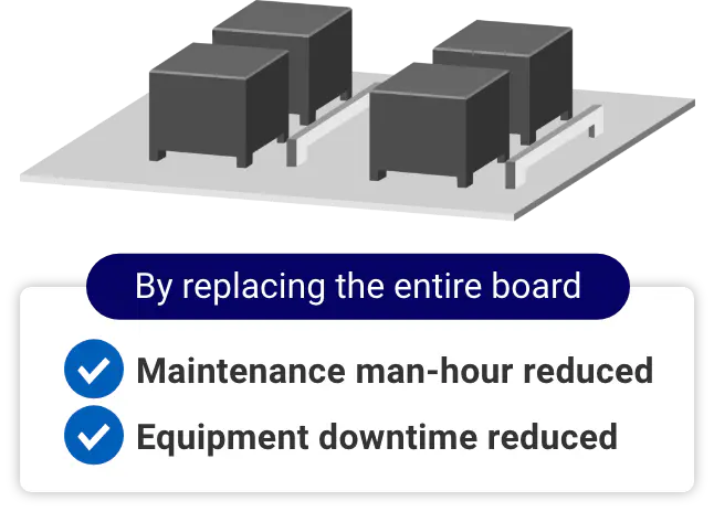
Maintainability
PCB relays are mounted on the board by soldering, making pinpoint component replacement difficult in the event of failure. In many cases, the entire circuit board is replaced.
You might think that replacing the entire circuit board would be more expensive than replacing only the faulty component. However, since the entire board is new, it can be replaced in a single replacement without the need to send workers to the site to identify the faulty component. The time required for replacement work can be reduced, resulting in improved equipment uptime.

Vibration resistance
The contactor has a highly robust structure that increases contact pressure and is resistant to vibration. For this reason, contactors are often used in automotive and other applications. Their proven track record has been recognized and utilized in other applications with high vibration characteristics. High-capacity PCB relays can also be made more vibration-resistant by devising contact shapes, etc. If you have any requests, please feel free to contact us.
What are the key points for designing PCB relay mounting boards?
When considering integration onto a circuit board, you may be asking yourself, “What kind of components are needed?”, “Is it okay to energize the board with a large current?” and so on. Please refer to the following articles for design tips.

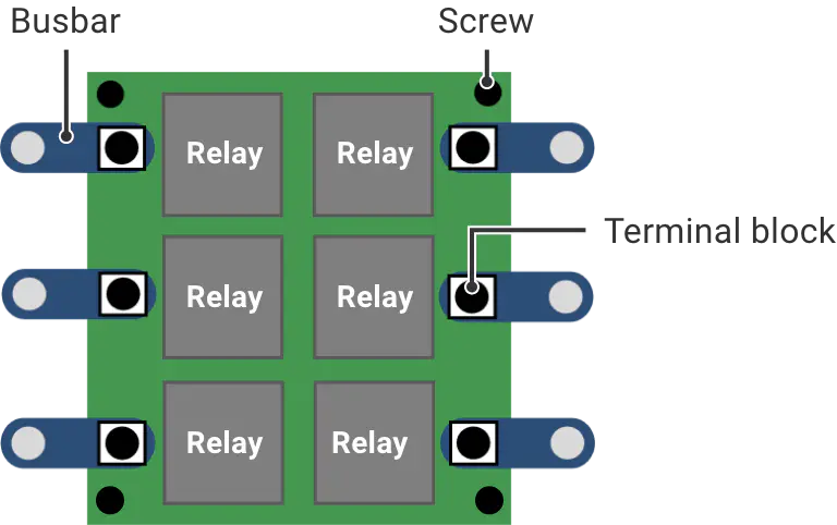
Example of peripheral components required for high current control system utilizing PCB relays
The following is an example of required components for a relay PCB module (when used with three sets of two 1a contacts in series). A component such as a thick copper board capable of carrying a large current is required.
| Component | Pieces |
|---|---|
|
Relay (SPST-NO (1a)) * Less in number of components in case of multi-pole relay |
6 |
|
Printed circuit board (thick copper board) |
1 |
| Busbar | 6 |
| Terminal block | 6 |
| Screw | 4 |

PCB design, mounting conditions
●Board design conditions considering heat generation and dissipation
In addition to high-density mounting on a board, it is important to adopt a board that fits the component layout and conditions if you want to energize the device with a large current. In general, the design should take into account the appropriate board thickness, copper foil cross-sectional area, terminal block size, and distance between main terminals for the rated current of each relay. For detailed condition examples, please refer to the link on the right.
●Mounting conditions for printed circuit board terminals
To keep the terminals from rising in temperature and overheating, high-capacity PCB relays may require terminals with a large surface area. For the concept and recommended profile of how to solder mount on the board, please refer to the link on the right .

Heat measures
It is also important to minimize heat dissipation mechanisms such as fans and heat sinks by controlling the heat generated by the components themselves. Relays are sometimes regarded as components that generate heat relatively easily, but heat generation can be controlled by selecting relays with low contact resistance.
Our relays feature “low contact resistance and low heat generation”. We also offer a product (G9KA) that is capable of maintaining an initial value of less than 0.2 mΩ, which is equivalent to a contactor, and less than 0.3 mΩ after electrical durability. Simulation results show that replacing a conventional general high-capacity relay with our relay reduces the initial resistance by 0.2 mΩ, resulting in a temperature rise of approximately 19.3°C (G9KA) and 67.7°C (G9KA-E). Please consider this. (For details, click here)

Low power consumption by holding voltage circuit
It is recommended that high-capacity PCB relays be controlled by “holding voltage circuit” or “PWM drive circuit” to minimize power consumption. Depending on the circuit, it is theoretically possible to reduce the drive power to 1/4. For circuit examples, please refer to the links on the right or the white papers on each product page.
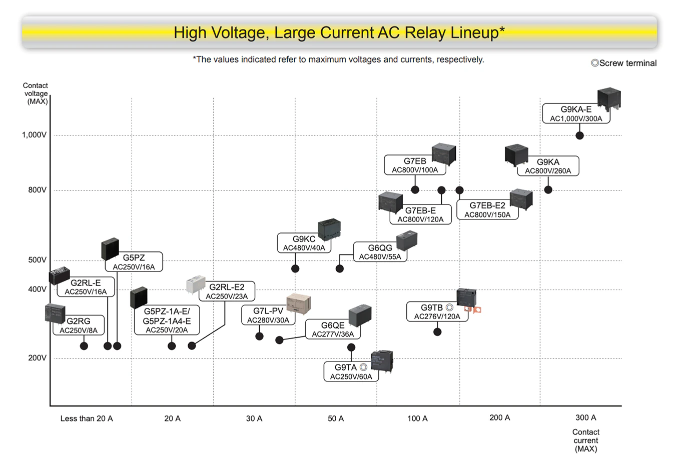
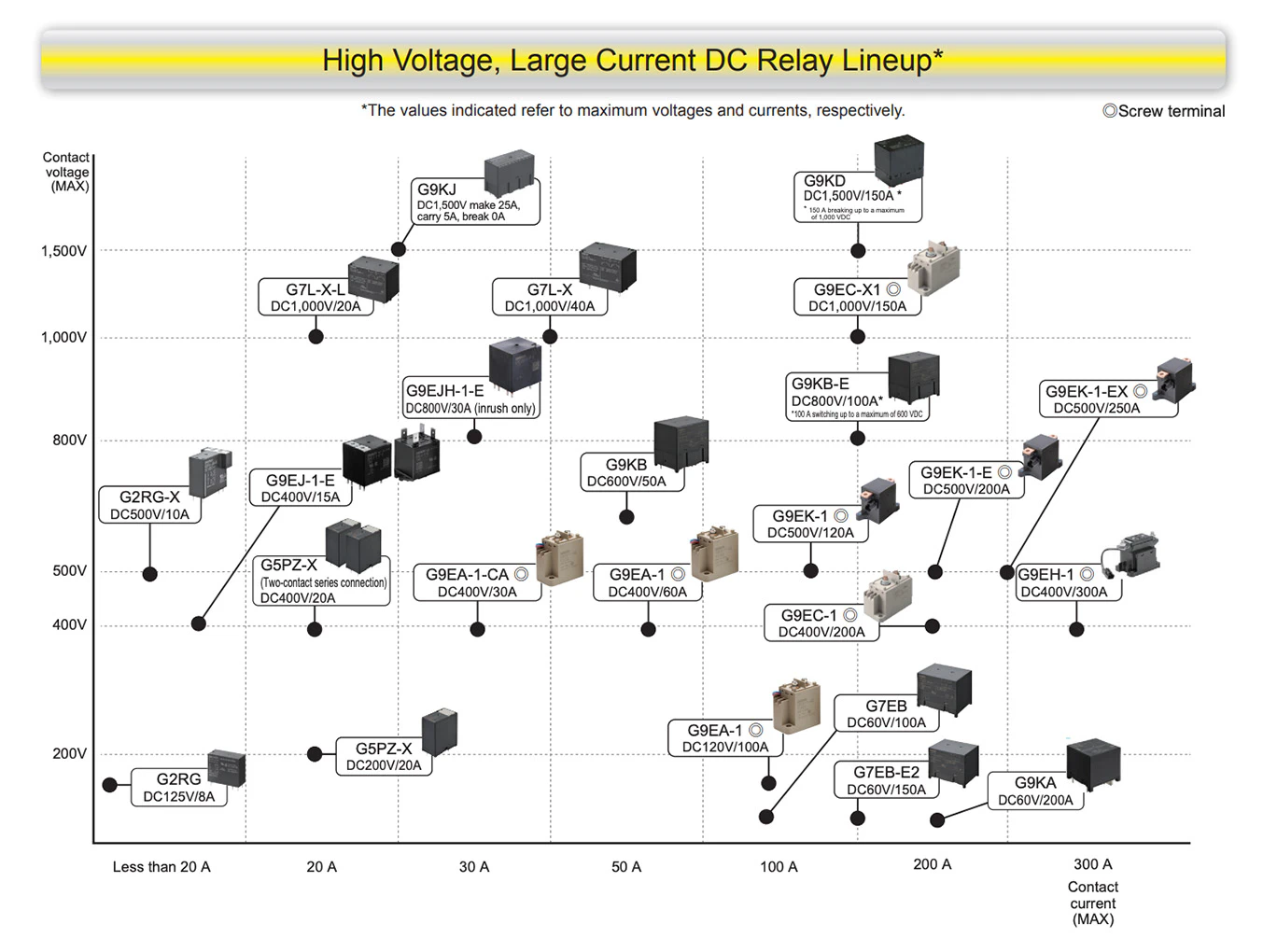
OMRON’s high-capacity mechanical relay lineup
OMRON’s high-capacity PCB power relays offer a product lineup suitable for a wide range of applications from low to high voltages. Select the optimum relay for your design.
Please feel free to contact us if you need help in selecting the right one.

Related contents
High Capacity Relay Technical Support Page
A technical support page for high-capacity relays that provides detailed explanations of “questions” when using PCB power relays with large current and high voltage, such as reverse voltage of coils, holding voltage application circuits, recommended conditions for large-current PCB flow soldering, effects of magnetic fields, and precautions when connecting in series or parallel.

Energy Market Solutions
OMRON will introduce the solutions that we provide to customers for related equipment from energy generation to utilization, categorized into “Commercial/Industrial” and “Household” applications.
