For more info.
With the acceleration of the spread of electric vehicles (EVs), demand is increasing for high-performance EV chargers that can use energy more effectively and without waste. This presentation introduces examples of solutions to equipment design challenges to realize these customer needs.
↓Click to see some of the contents
- AC EV charger
trend - AC EV charger
design challenges - Value provided
by OMRON products - Use for other
applications - Related contents
AC EV Charger Trend
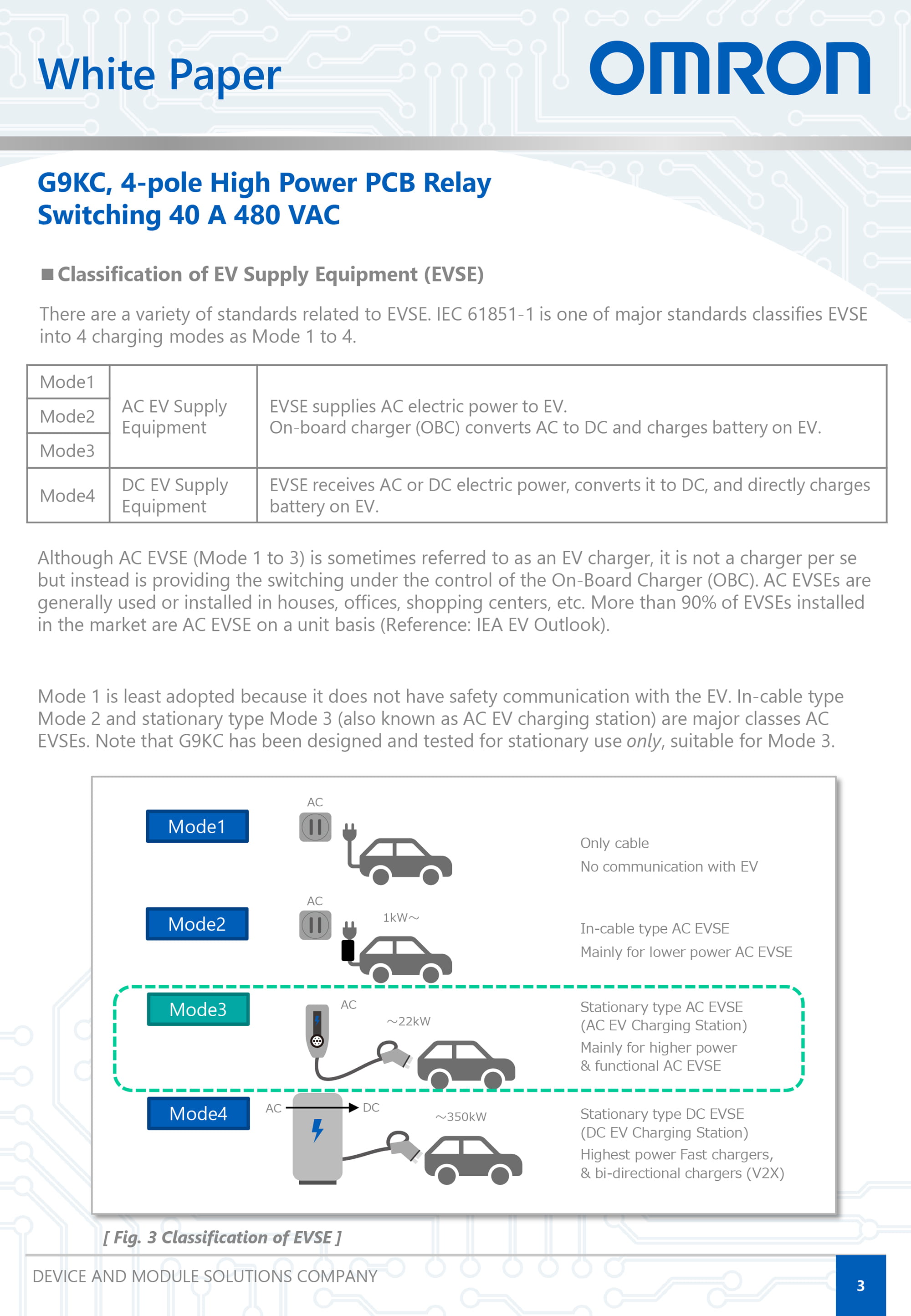
The trend in AC EV chargers include the need for higher output to reduce charging time, increased current, and three-phase compatibility. In addition, stationary AC EV chargers used in general households and commercial facilities require compact, slim, and lightweight equipment design in terms of installation, design, as well as improved productivity and cost reduction during assembly.
Trend towards higher output AC EV chargers
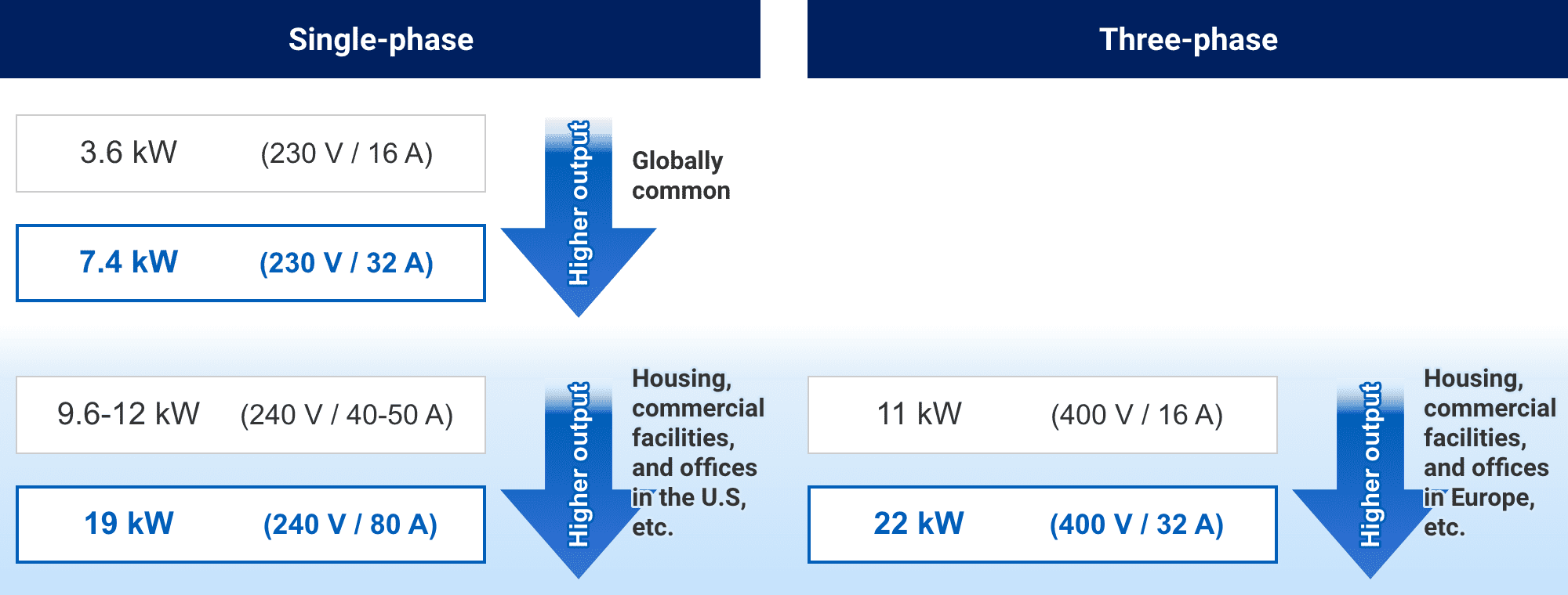
Note: According to OMRON's research in March 2024
AC EV Charger Design Challenges
(1) Avoiding a decrease in charging capability (issues when using power relays)
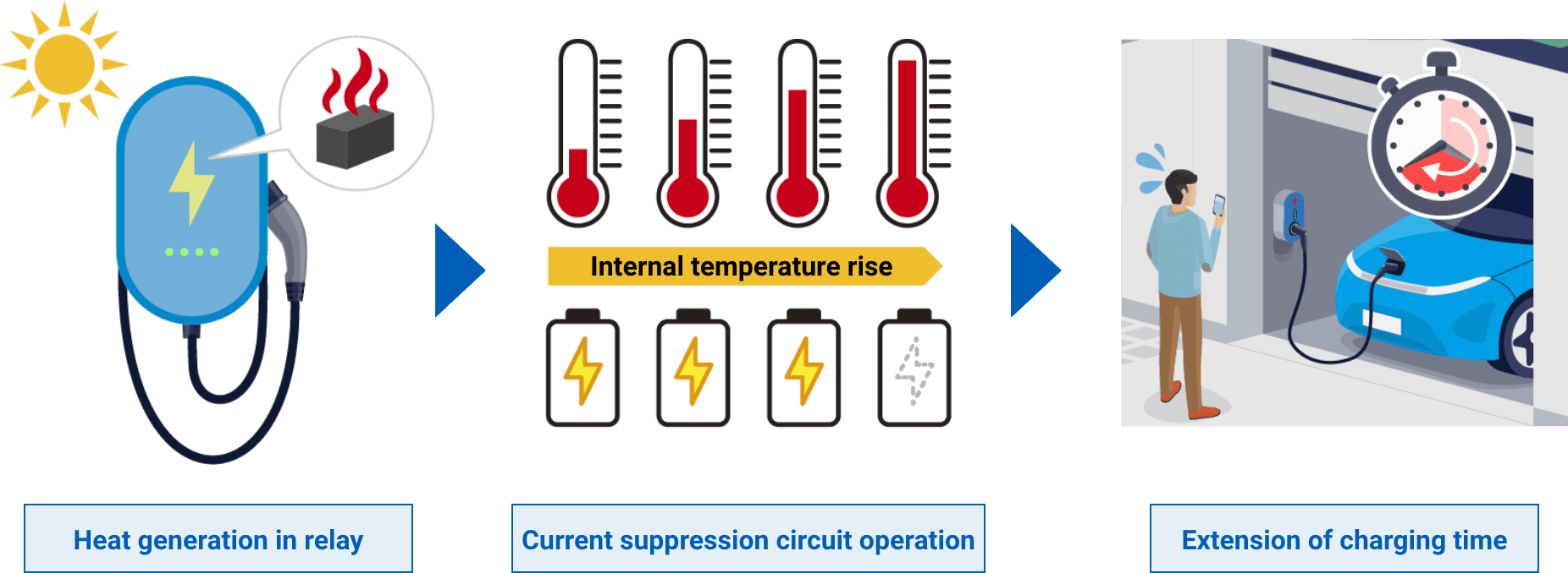
One of the challenges in increasing the output of AC EV chargers is the rise in temperature inside the housing due to heat generation of components. When the internal temperature of the equipment rises, the charging current suppression circuit operates, resulting in longer charging time and lower efficiency. In particular, relays tend to have higher contact resistance than contactors, so large currents generate more heat.
EV chargers are generally installed outdoors, and their housings are basically almost completely sealed to prevent water from entering. In addition, as chargers become smaller and slimmer, their housings become smaller, making it even more likely for the internal temperature to rise.
(2) Cost reduction of equipment, downsizing and weight reduction (issues when using a contactor)
In some cases, contactors are used to interrupt high-capacity circuits such as EV chargers. However, contactors are generally cable-wired, so there are issues with assembly productivity, such as the amount of wiring work required and the need to check for screw tightening and incorrect wiring. Furthermore, contactors are large in size and are not effective in designing smaller, slimmer, and lighter equipment.
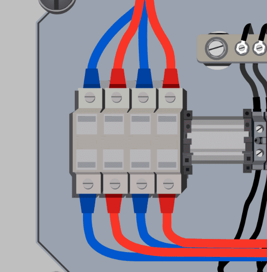
To solve this issue, it is necessary to select a relay with low contact resistance that will reduce heat generation.
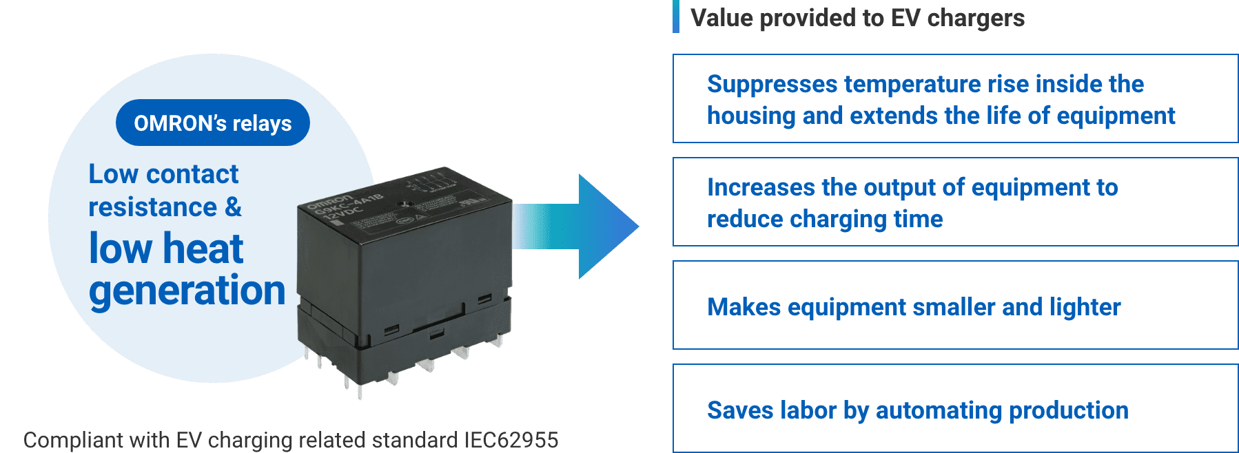
OMRON Products: Value Provided by G9KC
EV chargers compatible with three-phase, which are capable of supplying a large amount of power with high efficiency, are beginning to spread in residential housing in Europe, as well as in housing complexes, commercial facilities, and business establishments around the world.
In addition, higher output (22 kW [400 VAC/32 A 3Φ], etc.) is making steady progress to reduce charging time.
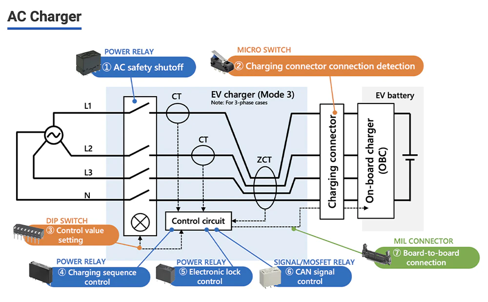
Typical Configuration of 3-phase AC EV Charging Station
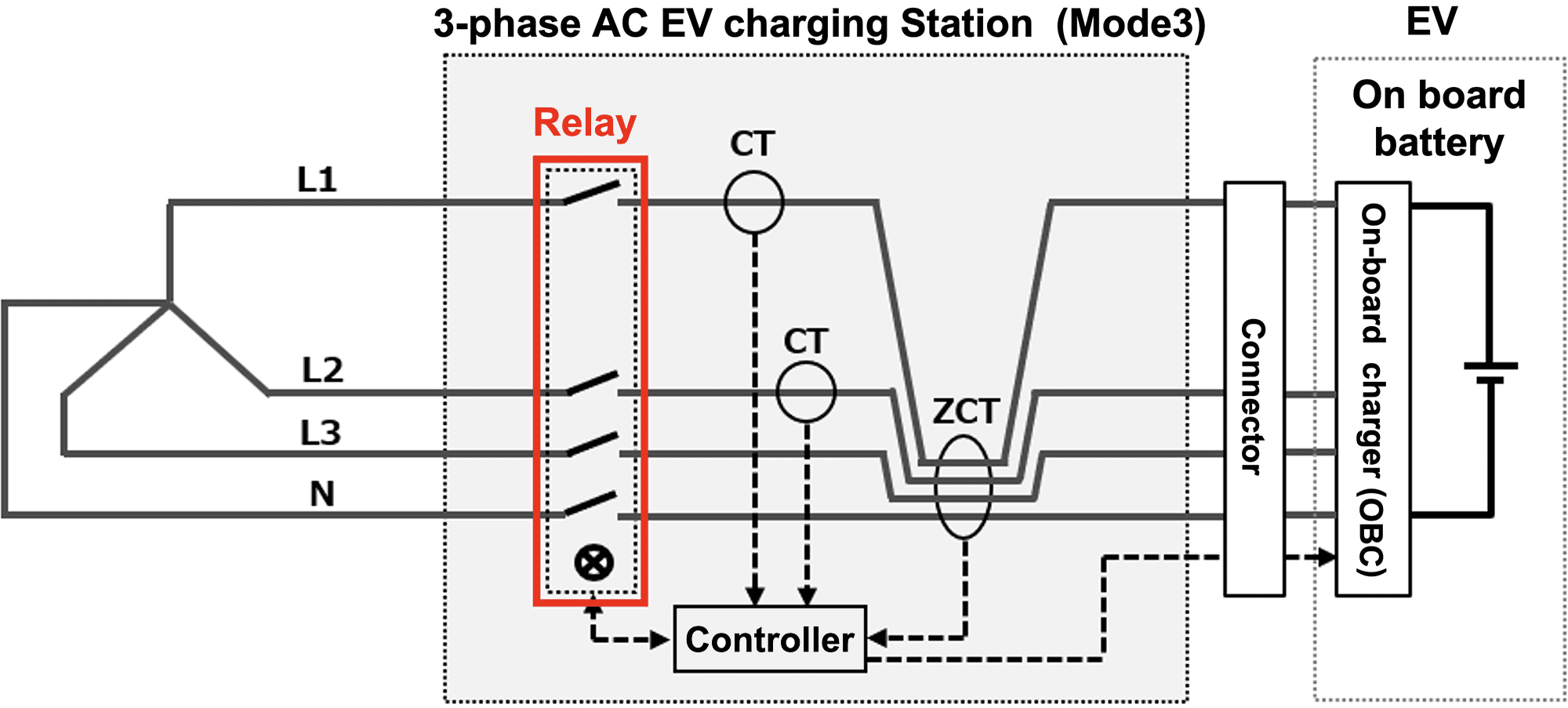
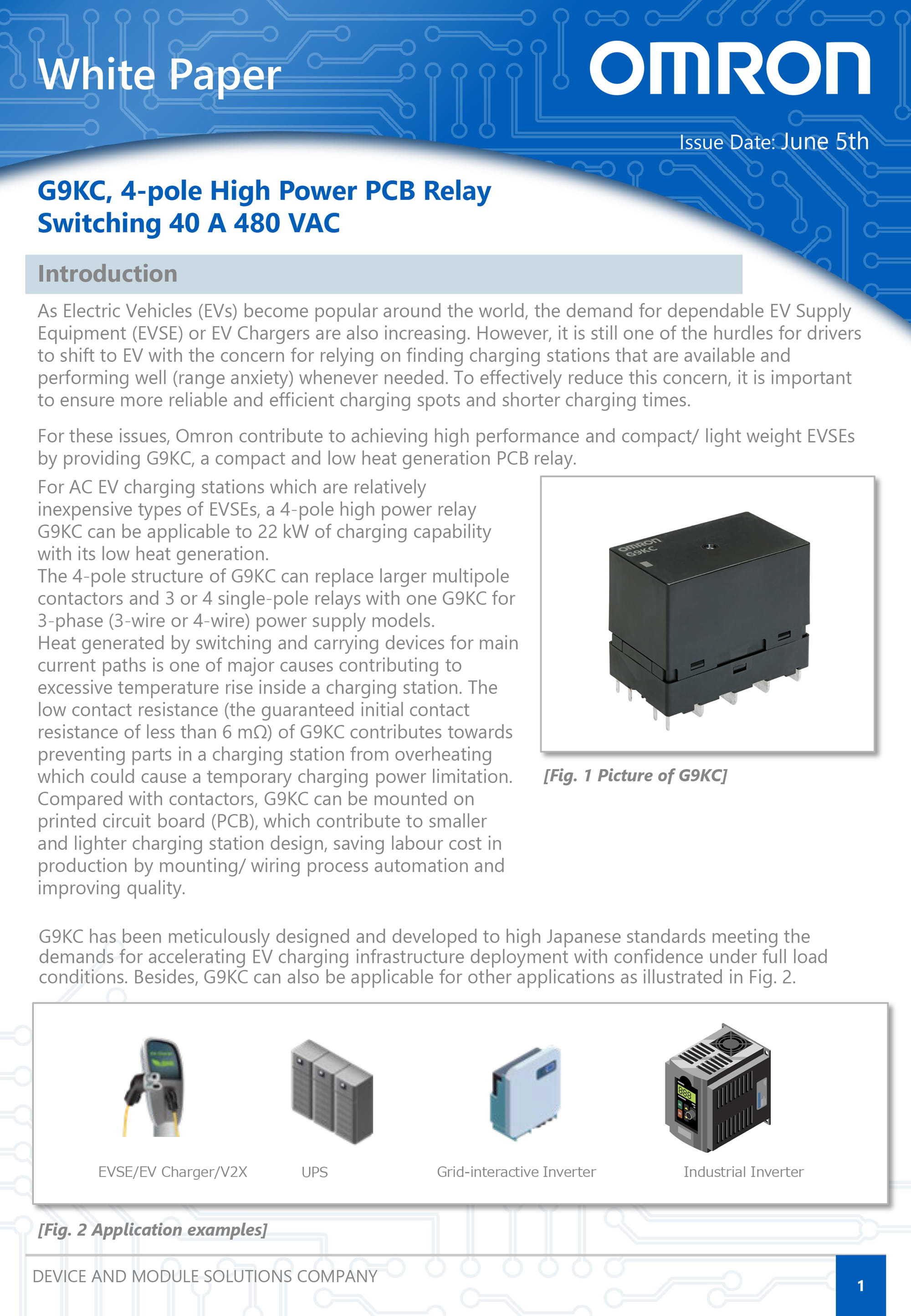
OMRON offers the compact 4-pole PCB power relay: G9KC that solves the issue with this three-phase EV chargers.
Value provided by power relay G9KC
(1) Longer equipment life through reduced thermal stress
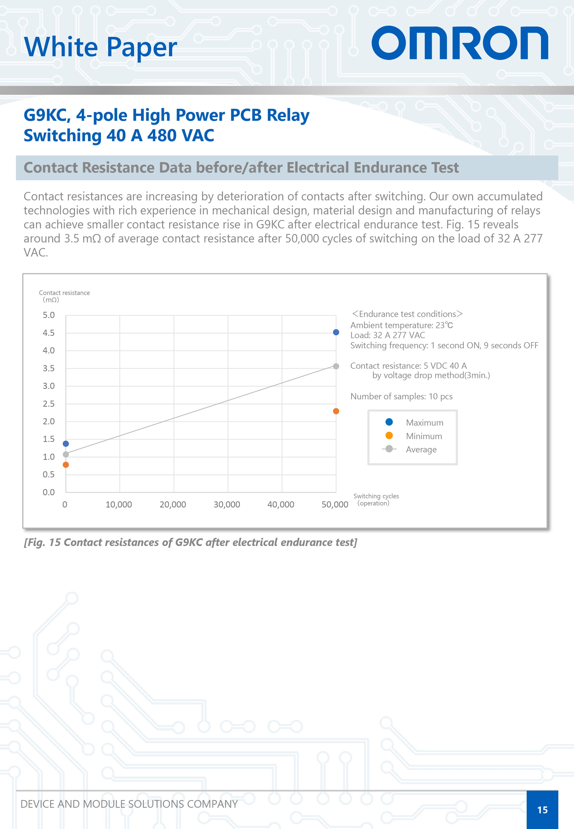
The G9KC has low contact resistance (initial value: 6 mΩ or less), which suppresses heat generation. This helps suppress local temperature rise in the charger housing, reduce the deterioration rate and failure risk of surrounding components due to heat, and extend the service life of the equipment. It also increases flexibility in PCB design.
・Click here for details on test data and other information regarding low contact resistance
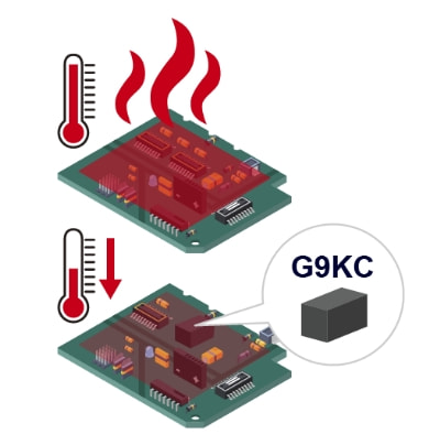
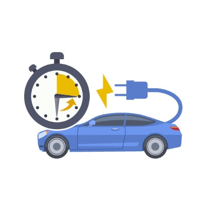
(2) Reduced charging time due to higher output of equipment
The G9KC generates low heat and suppresses the temperature rise inside the charger housing, which helps suppress charging current and avoid a reduction in charging capability due to overheating, contributing to the reduction of the design charging time.
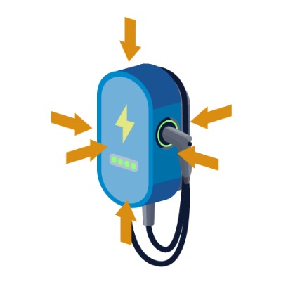
(3) Contributing to smaller and slimmer chargers
By switching the contactor to the compact power relay G9KC, the equipment housing can be made smaller and slimmer. When the charger housing size (surface area) is smaller, the temperature rises more easily and the allowable heat generation becomes lower, so a low-heat-generating relay with low contact resistance is effective in making the charger smaller and slimmer.
(4) Contributing to automated production and labor saving of chargers
By switching from the contactor to the PCB-mountable power relay G9KC, production can be automated.
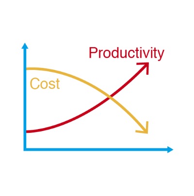
Reducing wiring man-hours and eliminating wiring mistakes can significantly improve productivity and reduce costs.
・Click here for temperature simulation data
G9KC specifications
| Item | Specification | Remarks |
| Contact form | 4PST-NO (4a) 4PST-NO (4a) + SPST-NC (1b) |
Auxiliary contact: IEC 60947-4-1 Compliant with mirror contact structure |
|---|---|---|
| Contact rating | 480 VAC, 40 A / 277 VAC, 32 A | Main contact |
| Contact resistance | 6 mΩ max. | Main contact, Initial value (23°C) |
| Contact gap | 3.6 mm min. | Main contact, Compliant with EV charger standards IEC61851-1 and others |
| Electrical durability | 277 VAC, 32 A 50,000 times 480 VAC, 40 A 30,000 times |
Main contact, Switching frequency: 1 second ON - 9 seconds OFF |
| Dimensions | W35 mm × L58 mm × H47 mm | Average dimensions |
| Terminal shape | PCB Terminals | 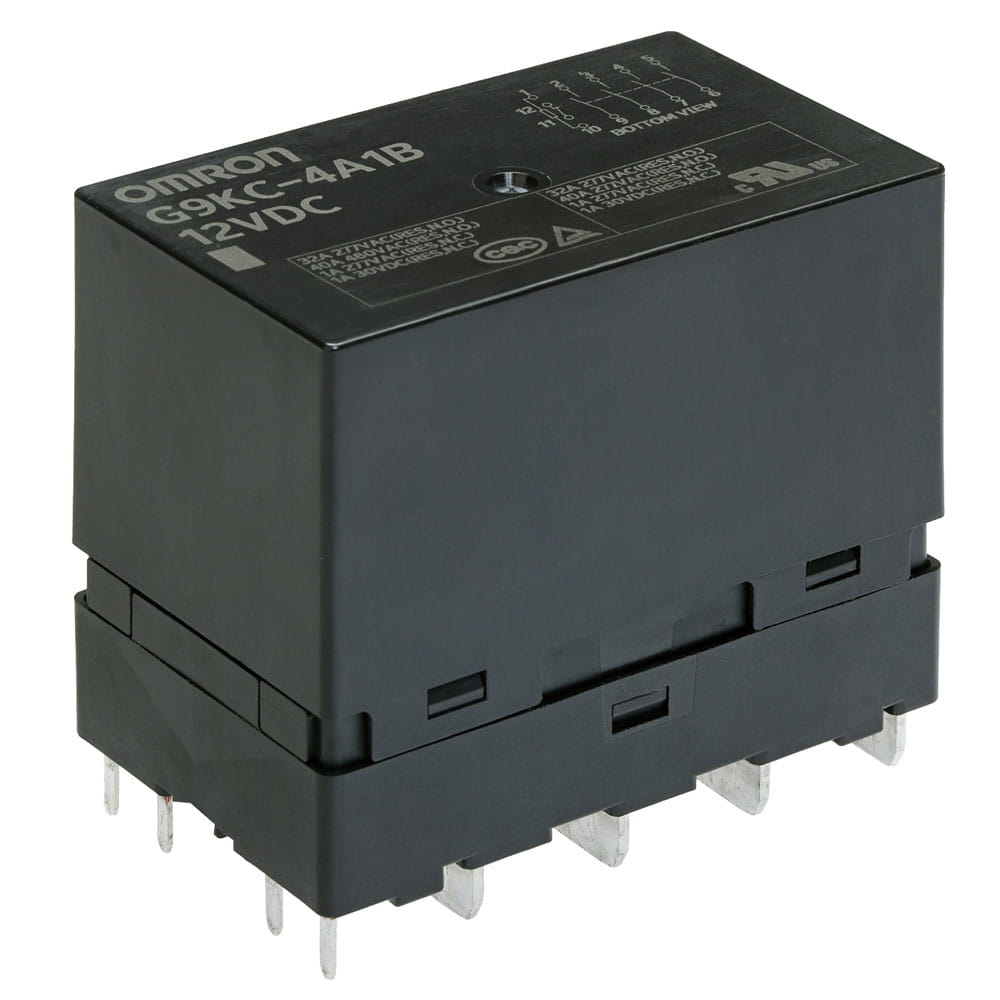 |
| Certified standards | UL/C-UL, EN/IEC, CQC | ー |
・Refer to the latest G9KC datasheet for details.
Use for Other Applications
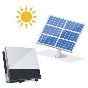
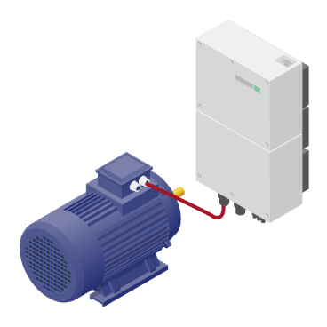
The power relay G9KC can be used for input/output switching of various devices as well as AC EV chargers.
PV
inverter
Industrial
inverter
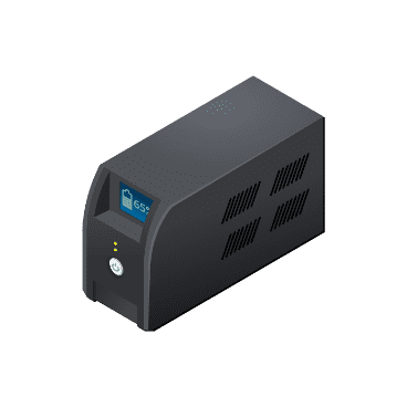
Uninterruptible power supply
Energy storage
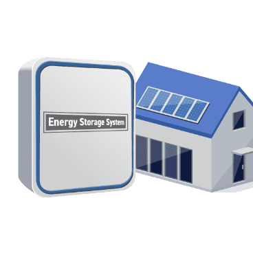
system
DC
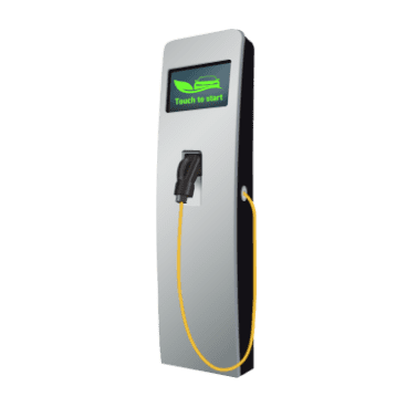
quick charger
* For applications for energy-related equipment, see Solutions for the Energy Market.
Related Contents
G9KC Power Relay Product Page
You can download data sheets, related contents, etc. for this product.
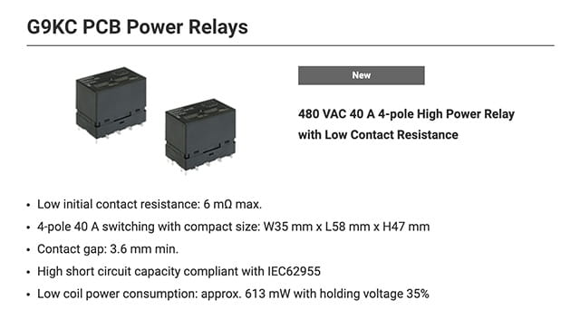
G9KC Power Relay White Paper
You can view detailed information about G9KC (market trends, applications, features and specifications, usage, performance data, etc.). Use this information for your design consideration.
Solutions for Energy Markets
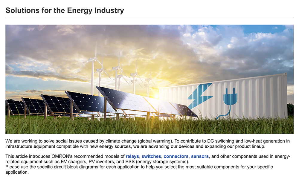
Products for energy-related equipment such as EV charging facilities, PV inverters, and energy storage systems are introduced.
High-Capacity Relay Technical Support Page
Our technical professionals explain in detail about “What is difficult to understand” when using PCB power relays with high currents and large voltages, including counter electromotive voltage, holding voltage application circuits, effects of the magnetic field, and precautions when connecting in series or parallel.

DMS PRODUCTS For GREEN Page

FAQs for Engineers
Frequently asked technical questions about our products are explained in an easy-to-understand manner using charts and illustrations with a structure of (1) answers, (2) explanations, and (3) one-point advice. Below are some typical examples of questions.
 Is there a relay with a function to hold the contact even if the coil voltage of the relay is turned off? (FAQE10007E)
 What do VDC and VAC on the relay case indicate? (FAQE10008E)
 What are surge countermeasures in coil relays? (FFAQE10041E)
 Can a relay be mounted in any direction? (FAQE10051E)
 What are the preheating and soldering temperature conditions for automatic soldering on PCBs? (FAQE10056E)
