Glossary of Electrical Relays
- Basics
- Technology
- Applications
- Standards
- Glossary
Explanations
B
- Bounce
-
Bouncing refers to the phenomenon in which intermittent openings and closings occur between contacts. This is caused by vibration or shock resulting from collisions between the moving parts (armature) and iron core or between contacts (JIS C5442).
C
- Coil inductance
-
(For general purpose relays only)
For a DC relay, inductance value is determined by the time constant when a rectangular wave is applied.
For an AC relay, inductance value is at the rated frequency.
Relays have different inductances for "pull-in" and "drop-out" states.
- Coil resistance
- This is the resistance of a coil measured between the coil terminals when the coil temperature is at +23°C.
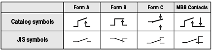
- Contact form
-
Contact forms refer to the contact mechanism.
Types of contact forms include Form B contacts (Break contacts), Form A contacts (Make contacts) and Form C contacts (Transfer contacts).
- Contact resistance
-
The contact resistance is a combination of the inherent resistance of the conductors that make up the armature, terminals, contacts, and other parts, the boundary resistance where the two contacts meet, and the concentrated resistance.
The contact resistances given in this catalog are the initial specified values. The size of the values do not indicate performance during actual operation.
The standard measuring method of contact resistance uses the voltage-drop method (four-terminal measurement) as shown in the drawing below at the designated measuring currents.Test Currents (JIS C5442)
Rated contact current or switching current (A) Test currents (mA) Less than 0.01 1 0.01 or more, less than 0.1 10 0.1 or more, less than 1 100 1 or more 1000 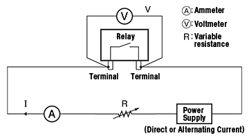
- Crosstalk characteristic
-
(Only for high-frequency PCB relays)
Indicates the degree of high-frequency signal leakage between the contact circuits.
D
- Dielectric strength
-
The maximum value before insulation damage occurs when voltage is applied for one minute to an isolated metallic part (especially charged metal part).
The voltage is applied at the same location as the insulation resistance.The leakage current (the current used to detect insulation damage) is normally 1 mA.
Sometimes, however, a leakage current of 3 mA or 10 mA is used.
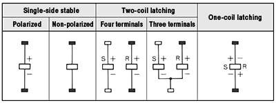
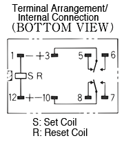
- Double-winding latching relays
-
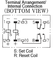
This type of relay has two coils: a set coil and a reset coil, with latching configuration to maintain the set or reset position.
E
- Electrical endurance
-
This is the durability of opening and closing of the contacts based on the specified switching frequency with load applied.
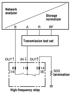
- Example of measuring high-frequency characteristics
-
Contacts that are not associated with the measurement are terminated at 50Ω.
F
- Failure rate
-
The percentage of failures per unit time (or number of operations) during continuous relay switching under individually specified test types and loads.
The rate may vary, depending on the switching frequency, ambient conditions and expected reliability level.
Users must test the relay under actual operating condition to verify its applicability.In this catalog, the failure rate is given as the P level (reference value). This expresses the failure level at a reliability level of 60% (λ 60) (JIS C5003).

- Flux protection (PCB relay)
-
This type of structure is designed to prevent flux from penetrating into the relay housing during soldering.
H
- Hermetically sealed (Plug-in relay)
-
This type of structure places the relay in a corrosion resistant sealed case using metal or glass purged with inert gas (N2) to protect from corrosive gas penetration.
- High frequency isolation
-
(Only for high-frequency PCB relays)
Indicates the degree of high-frequency signal leakage between contacts that are separated (in open position) and contact terminals in an open circuit.
- Hot start
-
This refers to the Must Operate voltage and/or the state of the current turned ON immediately after it has been turned OFF subsequent to continuous applying of current to a coil.
(The coil voltage, switching current, ambient temperature settings are based on the application conditions)
I
- Impulse withstand voltage
-
The maximum abnormal voltage that the relay can withstand when the voltage surges momentarily due to lightning, switching an inductive load, etc.
- Insertion loss
-
(Only for high-frequency PCB relays)
Indicates the loss of high-frequency signals between the contact terminals in a closed circuit.
- Insulation resistance
-
This is the resistance value between all isolated sections i.e. between coil and contacts, between conducting terminals and uncharged metallic parts (e.g. core frame, iron core), and between contacts.
This value is given for the relay and does not include lands on PCBs.- Between coil and contacts: Between coil terminal and all contact terminals
- Between contacts with different polarities: Between contact terminals of different polarities
- Between contacts with the same polarity: Between contact terminals with the same polarity
- Between set coil and reset coil: Between set coil terminal and reset coil terminal
L
- Latching relays
-
G6BU / G6BK
This type of relay switches to set state or reset state by input of pulse voltage. This state can be maintained during power interruption (including pulse voltage) until receiving inverting input.
*Remarks:
There are two types of mechanisms for maintaining the set and reset positions:
- Magnetic holding type
- Mechanical holding type
There are also two types of coils for applying the set and reset pulse voltages:
- Single-winding type
- Double-winding type
M
- Maximum high-frequency carry power
-
(Only for high-frequency PCB relays)
Indicates the maximum high-frequency carry power that can pass between contact terminals in a closed position.
- Maximum high-frequency switching power
-
(Only for high-frequency PCB relays)
Indicates the relay contact's maximum high-frequency switching power.
The electrical endurance becomes shorter than the rated load.
- Maximum switching capacity
-
This is the maximum load capacity allowable for a switch to function.
The circuit design must be arranged to maintain below this value when using the relay.
- Maximum switching current
-
This the maximum current allowable for a switch to function.
Be sure to not exceed this value during actual operation.
- Maximum switching voltage
-
This is the maximum voltage allowable for a switch to function.
Be sure to not exceed this value during actual operation.
- MBB contacts
-
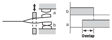
MBB (Make-Before-Break) contacts (shorting contacts) are part of a group of contacts with a specified operation sequence, designed to close before another contact can open. It is also sometimes referred to as "Form C1" contacts or "Continuous" contacts.
- Mechanical endurance
-
This is the durability of opening and closing of the contacts based on the specified switching frequency with no load applied.
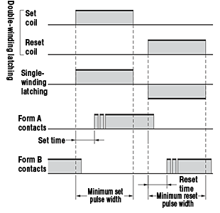
- Minimum pulse width
-
This is the minimum pulse width of the rated voltage applied to a coil required to set or reset a latching relay.
Note that this is a measured value at ambient temperature of +23°C and is not a guaranteed value.
- Must operate voltage (Pull-in)
-
This is the lowest possible level to allow a relay to operate (JIS C5442).
The value is measured at coil temperature of +23°C.
- Must release voltage (Drop-out)
-
This is the maximum coil voltage at which all contacts return to its de-energized positions when the voltage drops dramatically or gradually decreases (JIS C5442).
The value is measured at coil temperature of +23°C.(Example) Relay: MY4 DC-type
The distributions of Must Operate voltage and Must Release voltage are shown in the graph below.
As shown in the graph, the relay pulls in at less than 80% of the rated voltage and drop out at 10% or more of the rate voltage.Our catalog also indicates the "Must Operate voltage (pull-in)" at less than 80% and "Must Release voltage (drop-out)" at 10% or more.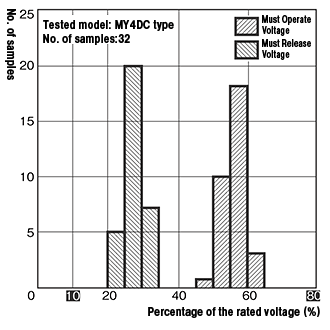
O
- Operate bounce time
-
This is the bounce time of Form A contact when rated coil voltage is applied, at which the coil temperature is +23°C.
- Operate time
-
This is the transition time from the moment rated voltage is applied to a coil to the moment contacts start to open and close. For multipole relays, unless otherwise specified, it refers to the moment rated voltage is applied to a coil to the moment the last set of contact starts (the slowest one) to open and close (JIS C5442).
Note that the time is measured at coil temperature of +23°C and does not include the bounce time.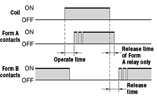
P
- Plastic sealed (PCB relay)
-
This type of structure is designed to prevent flux (during soldering) and cleaning solvent from penetrating into the relay housing.
- Plastic sealed (Plug-in relay)
-
This type of structure seals the case and cover with resin to minimize the effects in the case of a corrosive environment.
R
- Ratchet relays
-
(For general purpose relays only)
This type of relay is a stepping relay, which the contacts alternately switch ON and OFF with each input pulse.
- Rated carry current
-
This is the value of current which can be continuously applied to a relay contact without exceeding the maximum temperature limit when the contacts are not switched (according to JIS C4530).
- Rated current
-
This is the reference value of the coil current when a relay is used under normal conditions.
The value is measured at coil temperature of +23°C. The tolerance of the rated current is +15% and -20% unless specified otherwise for each model.
- Rated load
-
This is the reference value that determines the switching performance of the relay contact derived from the switching voltage and switching current.
- Rated power consumption
-
This is the power used by the coil at the rated voltage.
The rated power consumption for AC specifications is the value at a f60-Hz frequency.
- Rated voltage
-
This is the reference value applied to the operating coil when a relay is used under normal condition.
- Relay coil symbols
-
The symbols of each coil drive type are as shown below.
- Relay contact symbols
-
The symbols of each contact mechanism are as shown below.
- Release bounce time
-
This is the bounce time of Form B contact when rated coil voltage is applied, at which the coil temperature is +23°C.
- Release time
-
This is the transition time from the moment rated voltage is removed from a coil to the moment contacts are released.
For relays with more than one contact, the operating time is the time until the slowest contact operates, unless otherwise defined (JIS C5442).
For Form A contact only, it refers to the last Form A contact (the slowest one) opens.Note that the time is measured at coil temperature of +23°C and does not include the bounce time.*Related terminology: Bounce
- Reset time
-
(For latching relay only)
This is the transition time from the moment rated voltage is applied to a reset coil to the moment contacts are released (until the Form B contacts close).
For relays with only NO contacts, the release time is the time until the slowest NO contact opens.For multiple relays, unless otherwise specified, it refers to the moment rated voltage is applied to a coil to the moment the last set of contacts (the slowest one) is released.
Note that the time is measured at coil temperature of +23°C and does not include the bounce time.*Related terminology: Bounce
- Return loss
-
(Only for high-frequency PCB relays)
Indicates how much the high-frequency signals are reflected in the transmission path.
S
- Screw (metal) mounting relay (Enclosed) (Cased)
-
This type of structure places the relay in a sealed case designed to protect from contact with foreign substances.
- Screw (metal) mounting relay (Open)
-
This type of structure is designed to protect from contact with foreign substances and penetration.
- Set time
-
This is the transition time from the moment rated voltage is applied to a set coil to the moment contacts start to open and close. For multipole relays, unless otherwise specified, it refers to the moment rated voltage is applied to a set coil to the moment the last set of contacts starts (the slowest one) to open and close.
Note that the time is measured at coil temperature of +23°C and does not include the bounce time.
- Shock resistance
-
The shock resistance of a relay is divided into two categories:
Destruction, which quantifies the characteristic change of, or damage to, the relay due to considerably large shocks which may develop during the transportation or mounting of the relay, and malfunction durability, which quantifies the malfunction of the relay while it is in operation.
- Single-side stable relays (Standard type)
-
A relay which doesn't have any other special function on the operating elements besides switch ON and OFF depending on the non-excitation/excitation state of the coil.
G6B / MY
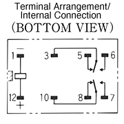
- Single-winding latching relays
-
This type of relay has one coil, with latching configuration to set and reset according to the polarity of the voltage applied to the coil and to maintain the set or reset position.
- Stepping relays
-
(For general purpose relays only)
This type of relay advances the switch position(ON/OFF) of multiple contacts in sequence with each input pulse.
- Stray capacitance
-
This refers to the electrostatic capacitance existing between terminals.
Ex: Stray capacitance Between A - C Form contacts Approx. 1pF Between C - C Form contacts Approx. 1pF Between C Form contact - coil Approx. 2pF
- Switching frequency
-
This is the number of times a relay can open and close over unit time.
T
- Thermoelectromotive force
-
When both ends of dissimilar metals come together under different temperatures between the two junctions, it allows the current to flow in a constant uniform direction in the circuit.
The electromotive force that generates this current is called the thermoelectromotive force. Thermoelectromotive force in a relay is generated between the dissimilar metals of terminals, contact segments and contacts.For thermocouple switching relay, thermoelectromotive force causes a gap between the actual temperature and the measured temperature.
- TV rating
-
The TV rating is one of the representative ratings approved by UL and CSA regulations to evaluate the inrush current withstand capability. The rating indicates the level of relay’s capability to switch the load, including the inrush current.
For example, relays for television power supplies need to obtain the TV rating.
The switching test (durability test) of these relays are performed using a tungsten lamp as a load and must withstand in total 25,000 times of the durability test.TV rating Inrush current Steady state current Example of product types TV-3 51A 3A G2R-1A TV-5 78A 5A G5RL-1A(-E)-LN TV-8 117A 8A G4W-1112P-US-TV8, G5RL-U1A-E, G5RL-K1A-E, G5Q-HR TV-10 141A 10A G7L
U
- Unsealed (Plug-in relay) (Cased)
-
This type of structure places the relay in a sealed case designed to protect the contact surfaces from foreign substances.
V
- V.S.W.R.
-
(Only for high-frequency PCB relays)
Indicates the voltage standing-wave ratio that occurs throughout the transmission path.
- Vibration resistance
-
categories: Destruction, which quantifies the characteristic changes of, or damage to, the relay due to considerably large vibrations which may develop during the transportation or mounting of the relay, and malfunction durability, which quantifies the malfunction of the relay due to vibrations while it is in operation.
α=(2πf)2×A×10-3
α Acceleration of vibration (m/s2) f Frequency (Hz) A Single amplitude (mm)
- Basics
- Technology
- Applications
- Standards
- Glossary
Click here for the relay product lineup