Photomicrosensor Basics: Design Ⅰ (Design for Emitter side)
- Basics
- Terminology
- Design
- Precautions
This chapter explains how systems using Photomicrosensors must be designed.
Characteristics of Emitter
The emitter of each Photomicrosensor (photointerrupter) consists of either an infrared LED or a visible red LED.
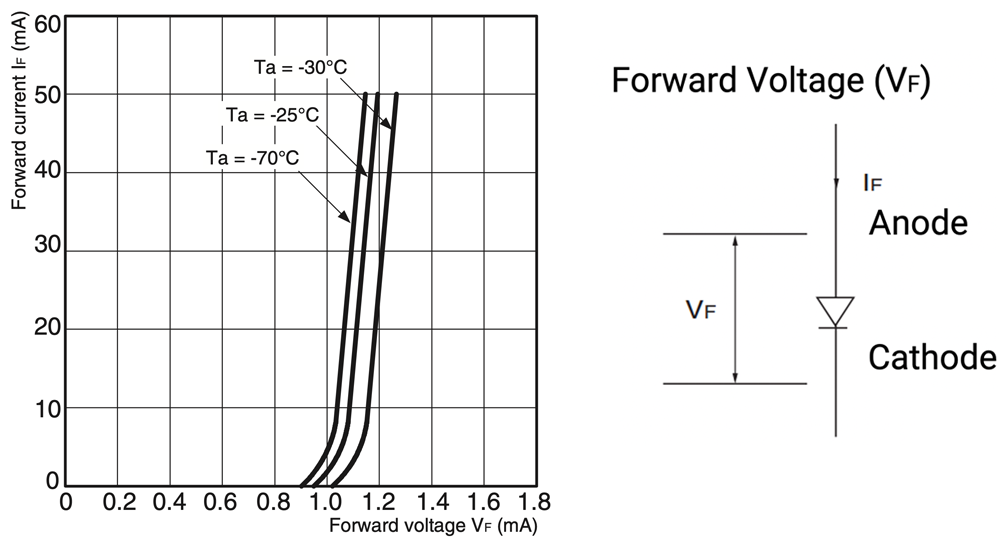
Figure 3 below shows the characteristics of the LED forward voltage (VF) for the EE-SX1081 (with an infrared LED). This graph indicates how the voltage drop of the LED is changed by the LED forward current (IF) flowing from the anode to cathode. The Light Emitting Diode is forward biased.
The forward voltage (VF) of this particular infrared LED is approximately 1.2 V.
The (VF) of red LED’s is typically greater than that of infrared LED’s - - their (VF) is about 1.8 to 2 V.
Figure 3. Forward Current vs.
Forward Voltage Characteristics (Typical)
Driving Current Level
First, it is especially important to design the level of the LED’s forward current (IF) so that it doesn’t exceed the rated Absolute Maximum Value. Before using any Photomicrosensor (photointerrupter), refer to the Absolute Maximum Ratings table in the datasheet to find the upper limit of the LED’s forward current.
For example, the first item in the Absolute Maximum Ratings table of EE-SX1081 shows that the forward current (IF) of its emitter is 50 mA max. at a Ta (ambient temperature) of 25°C. This means the (IF) of the LED should be 50 mA or less at 25°C.
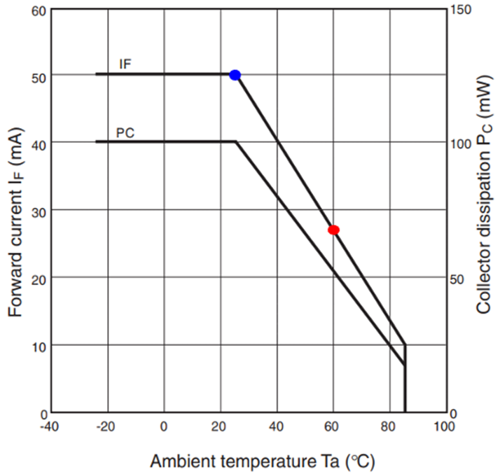
As shown in Figure 4, the value of (IF) must be reduced according to changes (increases) in the ambient temperature. Figure 4 indicates that the forward current (IF) should be about 27 mA maximum if EE-SX1081 is used at 60°C. This means that a current exceeding 27 mA must not flow through the LED at a Ta of 60°C. Otherwise, the LED will be destroyed, or its life will be greatly reduced.
Figure 4. Temperature Characteristics EE-SX1081
■ Absolute Maximum Ratings (Ta = 25℃)
| Item | Symbol | Rated value | |
|---|---|---|---|
| Emitter | Forward current | IF |
50 mA (see note 1) |
| Pulse forward current | IFP |
1 A (see note 2) |
|
| Reverse voltage | VR | 4 V | |
| Detector | Collector-Emitter voltage | VCEO | 30 V |
| Emitter-Collector voltage | VECO | --- | |
| Collector current | IC | 20 mA | |
| Collector dissipation | PC |
100 mW (see note 1) |
|
| Ambient temperature | Operating | Topr | -25℃ to 85℃ |
| Storage | Tstg | -30℃ to 100℃ | |
| Soldering temperature | Tsol |
260℃ (see note 3) |
|
Note 1. Refer to the temperature rating chart if the ambient temperature exceeds 25°C.
Note 2. The pulse width is 10 μs maximum with a frequency of 100 Hz.
Note 3. Complete soldering within 10 seconds.
Second, the lower limit of the LED forward current (IF) must be 4 mA if the emitter is an infrared LED and 2 mA for a red LED. If the value of (IF) is too low, then the optical output of the LED will not be stable. Not enough light is produced by the LED for proper detection of that light by the output element.
Third, the output’s light current (IL) is one of the most important characteristics for the Photomicrosensor (photointerrupter). If the specified value of (IF) from the datasheet’s Electrical and Optical Characteristics table is chosen for the design, then the corresponding values of (IL) range produced by the output detector will allow the output circuit of the Photomicrosensor (photointerrupter) to be designed easily.
To find the ideal forward current value of the Photomicrosensor’s LED, refer to the specified conditions for the light current (IL) shown in the datasheet. The (IL) range shown indicates the relationship between the forward current of the LED and the output of the detector (phototransistor), depending on various production lots.
For example, a forward current (IF) of 20 mA is specified as the condition of the light current (IL) in the datasheet of EE-SX1081. A current of 20 mA is the recommended value of forward current (IF) to use for EE-SX1081.
■ Electrical and Optical Characteristics (Ta = 25℃) EE-SX1081
| Item | Symbol | Value | Condition | |
|---|---|---|---|---|
| Emitter | Forward voltage | VF | 1.2 V typ., 1.5 V max. | IF = 30 mA |
| Reverse current | IR | 0.01 μA typ., 10 μA max. | VR = 4 V | |
| Peak emission wavelength | λP | 940 nm typ. | IF = 20 mA | |
| Detector | Light current | IL | 0.5 mA min., 14 mA max. | IF = 20 mA, VCE = 10 V |
| Dark current | ID | 2 nA typ., 200 nA max. | VCE = 10 V, 0 ℓx | |
| Leakage current | ILEAK | --- | --- | |
| Collector–Emitter saturated voltage | VCE (sat) | 0.1 V typ., 0.4 V max. | IF = 20 mA, IL = 0.1 mA | |
| Peak spectral sensitivity wavelength | λP | 850 nm typ. | VCE = 10 V | |
| Rising time | tr | 4 μs typ. | VCC = 5 V, RL = 100 Ω, IL = 5 mA | |
| Falling time | tf | 4 μs typ. | VCC = 5 V, RL = 100 Ω, IL = 5 mA | |
Design Method
Figure 5. Basic Circuit
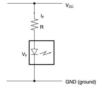
The following explains how the circuit constants must be determined. Figure 5 shows a basic circuit that drives the LED incorporated by a Photomicrosensor (photointerrupters). The basic circuit absolutely requires the addition of an external limiting resistor (RF). If the LED is imposed with a forward bias voltage without the limiting resistor, the current through the LED will be theoretically limitless (much greater than the Absolute Maximum) because the forward impedance of the LED is low. As a result, the LED will burn out.
Some users ask OMRON about the appropriate forward voltage to be imposed on the LED of the Photomicrosensor (photointerrupter). There is no upper limit of the forward power supply voltage (VCC), if an appropriate limiting resistor is connected to the LED. There is, however, the lower limit of the forward voltage imposed on the LED. As shown in Figure 3, the lower limit of the voltage must be more than the maximum value of the LED’s forward voltage (VF) specified in the datasheet (approximately 1.2 to 2 V), or no forward current will flow into the LED. In this example, (VCC) must be much greater than (VF).
least approximately 2 V for infrared LEDs and 3 V for red LEDs.
Typically, the supply voltage of a standard electronic circuit is 5 VDC minimum. However, the supply voltage (VCC) must be set to a value higher than the forward voltage (VF) of the LED, and should be at least approximately 2 V for infrared LEDs and 3 V for red LEDs. A system incorporating any Photomicrosensor (photointerrupter) must be designed by considering the followings:
- ・Forward current (IF)
- ・Limiting resistor (RF)
As explained above, determine the optimum level of the LED forward current (IF).
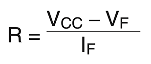
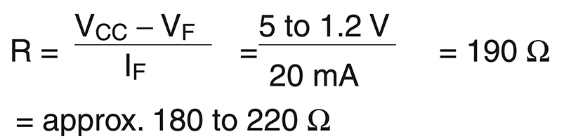
The recommended value of (IF) for the EE-SX1081, for example, is 20 mA. Therefore, the limiting resistor value must be decided so that the forward current (IF) will be approximately 20 mA. The resistance of the limiting resistor (RF) is obtained from the following equation:
In this case 5 VDC must be substituted for the supply voltage (VCC). The forward voltage (VF) obtained from Figure 3 is approximately 1.2 V when the IF is 20 mA. Therefore, the following resistance is obtained:
The forward current (IF) varies with changes in the supply voltage (VCC), forward voltage (VF), or resistance. Therefore, make sure that there is some margin between the absolute maximum ratings and the actual operating conditions of the Photomicrosensor (photointerrupter).
Figure 6. Reverse Voltage Protection Circuit
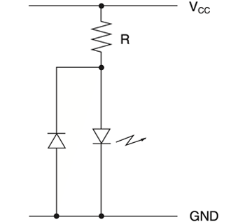
Because the limiting resistor (RF) and the LED are in series as shown in Figure 5, their positions are interchangeable. If the LED is imposed with reverse voltages (reverse biased), including noise and surge voltages, then a rectifier diode should be added in reverse parallel to the LED as shown in Figure 6.
LEDs can be driven by pulsed voltages, however the method is rarely applied to built-in Photomicrosensors for consumer and commercial devices. The details for the LED pulse drive method are not described here.
The following are important points required to operate any Photomicrosensor(photointerrupter):
- The LED’s have a forward voltage (VF) of approximately 1.2 V for an infrared LED and about 2 V for a red LED.
- The ideal level of the LED forward current (IF) should be determined based on the optimal design conditions described above.
- Determine the value of the limiting resistor (RF) after deciding the value of the forward current (IF), for the actual supply voltage, (VCC).
- If the LED is subjected to a reverse voltage, connect a rectifier diode to the LED in parallel with and in the direction opposite to the direction of the LED’s anode and cathode.
- Basics
- Terminology
- Design
- Precautions
Click here for the photomicrosensor product lineup