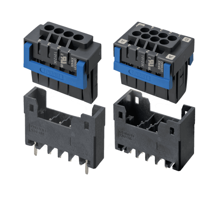
Push-In Terminal Block PCB Connectors
Designed with a Unique Dual-Spring Structure for Enhanced Ease of Use XW4M/XW4N
What is a Push-in Terminal Block PCB Connector?
Push-in terminal block is a type of terminal Block that can be connected simply by inserting the wires. Its main feature is the reduction of wiring workload.
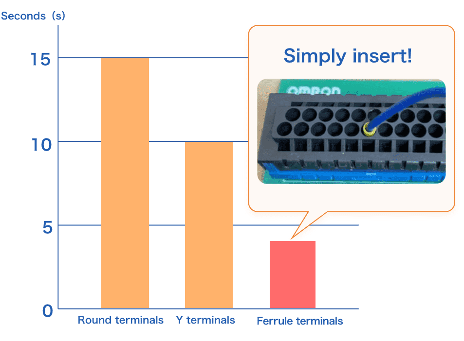
Substantial reduction of connecting workload
Connecting workload can be reduced by over 60% when connecting round terminals and Y terminals with screws and connecting ferrule terminals by push-in insertion.
Determined by research conducted in February 2021 by Omron
No retightening required
If screw terminal blocks are used, it is said that retightening is required 3 times on average, at the time of manufacturing, transportation and installation. Since the push-in terminal block does not have screws, it is possible to reduce the retightening workload to zero.
Benefits of XW4M/XW4N
Reduction of cycle time
- Easy insertion and removal by pushing the lever
- Light insertion and removal force helps reduce troubles such as pin warpage due to twisting
- Easy operation facilitates continuity check and shipping inspection in an official residence
Save space and reduce workload
- If multiple terminal Blocks with a small number of poles have been added, space saving and cost reduction are achieved by combining multiple poles into one.
- No additional processing is required due to the standard pin number marking
- Reduced man-hours by supporting reflow
Easy operation
- Connector type (plug/socket) allows you to perform wiring anywhere
- One-touch wiring is made possible by simply inserting the wires with ferrule terminals
- Push-in design is maintenance free, requiring no torque management and tightening as compared to screws
Features of XW4M/XW4N
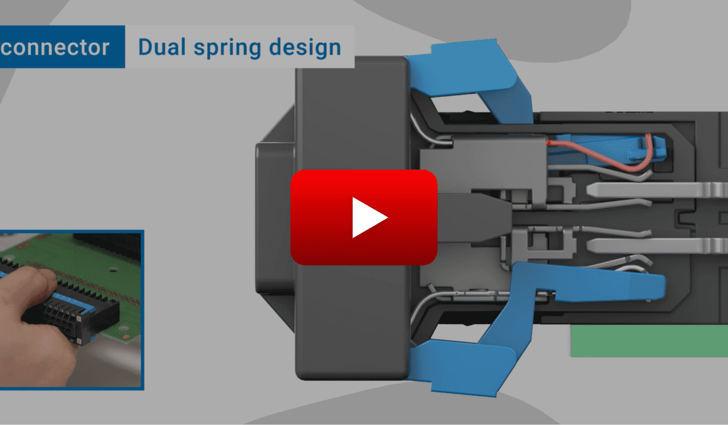
Feature 1Unique dual-spring structure *1
Easy insertion & removal, high contact reliability
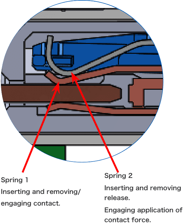
Unique dual-spring structure
Structure of conventional connectors
The contact parts of conventional products will receive the contact force needed for engaging the wings one by one on each side, thus making it difficult to reduce the insertion and removal force.
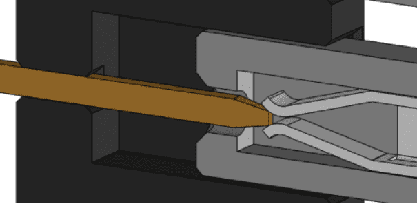

OMRON’s unique dual-spring structure
The unique dual-spring structure allows you to control the contact force, thus reducing the contact force of the connector and ensuring the contact force needed for engaging.
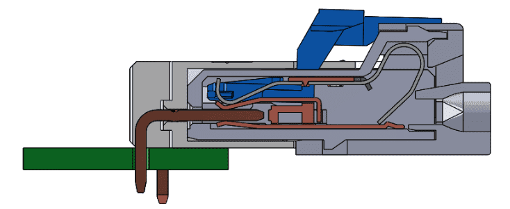
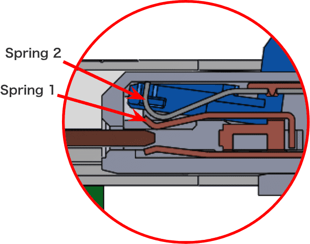
State of the unique dual-spring structure during connector operation
Connector
inserting/removing
The second spring is released and the insertion and removal force is reduced by pushing the detachable lever (blue)
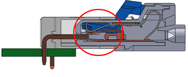
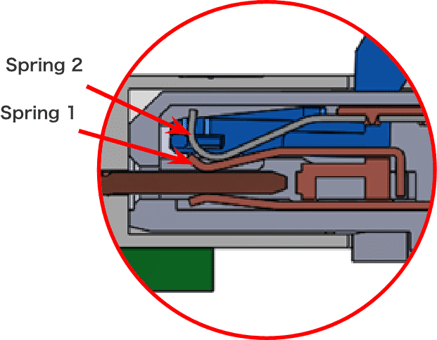
Connector
engaging
Contact reliability is ensured by applying the force of the second spring to the first spring

Watch the video for a detailed explanation of the unique
dual-spring structure
*1 Unique dual-spring structure: A structure that ensures contact reliability through the combined contact force of the first and second springs when engaging, and reduces the insertion and removal force by operating the lever to open the second spring when inserting and removing.
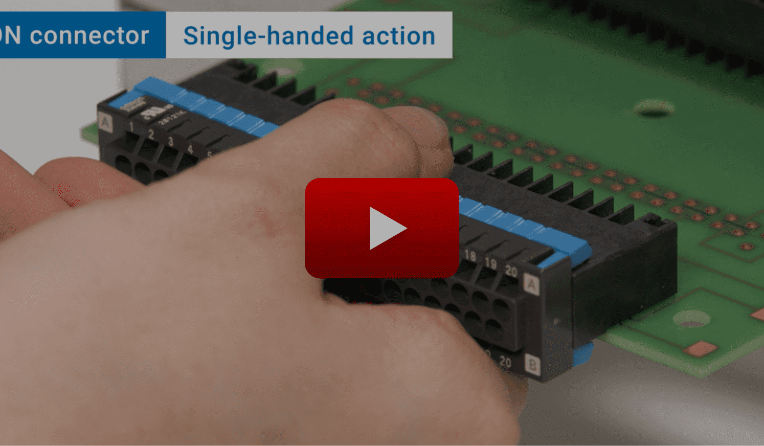
Feature 2Single-handed action
Easy single-handed connector insertion and removal
With the detachable lever installed in the direction of the connector handle, you can easily insert and remove the connector with one hand.

Watch the video for a detailed explanation of one-hand action
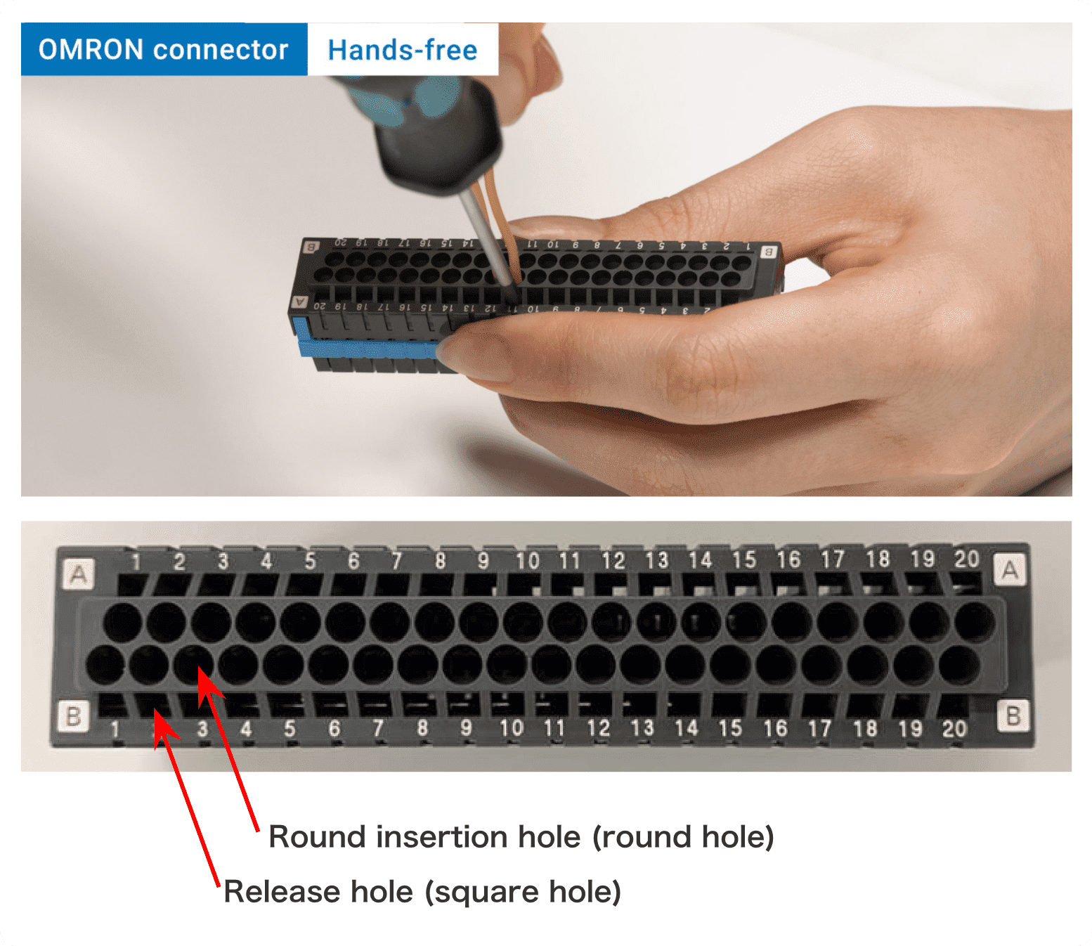
Feature 3Hands-free
Makes it easy to connect wires
With a release hole prepared for holding the screwdriver, it is possible to perform cable wiring with two hands.
Watch the video for a detailed explanation of hands-free mechanism

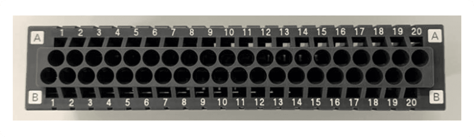
Feature 4The product comes standard with pin number markings *2
The product comes standard with pin number markings required for connector wiring, which eliminates the need for printing on other spaces such as a board, thus reducing unnecessary space and workload.
*2 Available for XW4N only.
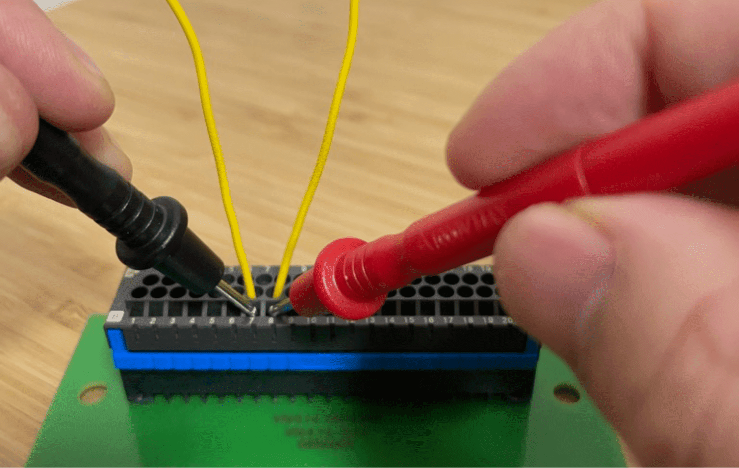
Feature 5Allows for checking continuity in the wired state
By using the release hole, it is possible to check the continuity even when the cable is wired.
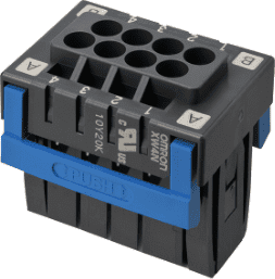
Product lineup
Please swipe the table.
| Row | Single-Row | Double-Row | ||
|---|---|---|---|---|
| Number of contacts | 2 to 20 poles *Except for 19 poles | 4 to 40 poles *Even number of pins except for 38 pins | ||
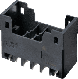
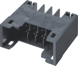
| Model | Straight Terminals | Right-Angle Terminals | Straight Terminals | Right-Angle Terminals |
| XW4M-□□D1-V1D□ | XW4M-□□D1-H1D□ | XW4M-□□D2-V1D□ | XW4M-□□D2-H1D□ | |
| Plug | 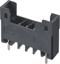 |
 |
 |
 |
| Model | XW4N-□□D1-□ | XW4N-□□D2-□ | ||
| Socket | 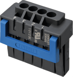 |
 |
||
* The value in □□ represents the pole number.
* Refer to the datasheet for details
Application Examples
Extensively used in various applications from FA equipment to industrial equipment.
-
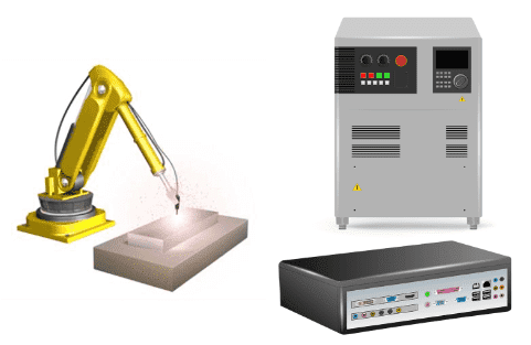
Robot Controller -
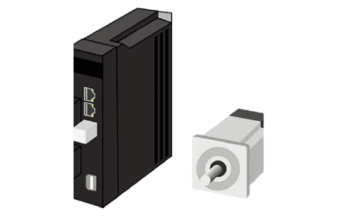
AC Servo Driver -
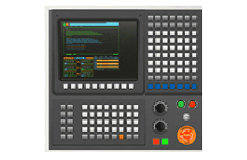
NC Devices -
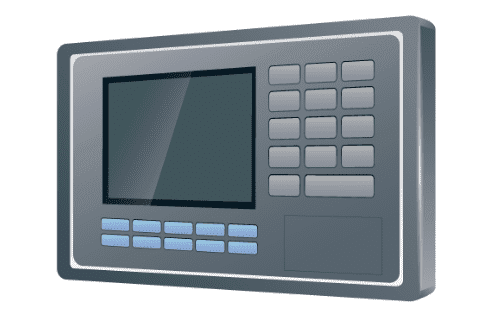
Programmable Display -
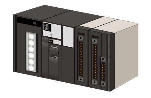
PLC -
Programmable Display -
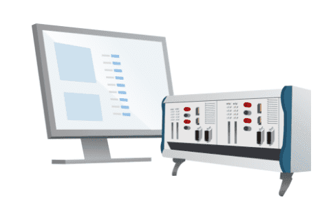
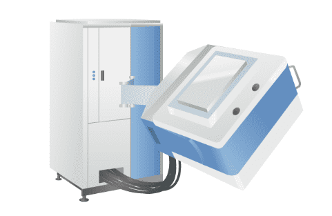
Measuring Instruments Machines -
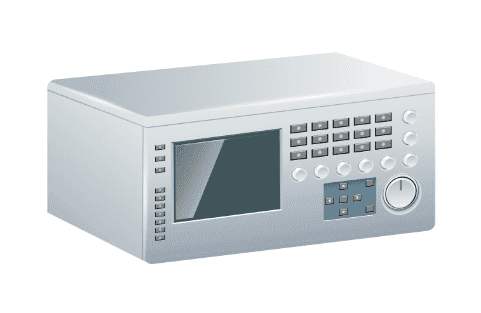
Inspection machines