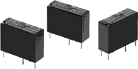
G5NB PCB Power Relay
A Miniature Relay with 1-pole
3A/5A Switching Capability and
10 kV Impulse Withstand Voltage
- Highly efficient magnetic circuit for high sensitivity (200 mW).
- Standard model conforms to UL/CSA/VDE standards.
- Satisfies EN61010 reinforced insulation requirements.
- IEC/EN 60335-1 conformed. (-HA Model)
- Conforms to IEC/EN60079-1, IEC/EN60079-15.
(IEC/EN) 60079-1 clause 15.5 Enclosed-break devices (Group IIA) testing passed.
(IEC/EN) 60079-15 clause 11.2 Sealed devices testing passed. - Reduced power consumption with voltage holding and pulse width modulation (PWM) control (Only for G5NB-@-PW model)
Related Contents

DOWNLOAD
This web page provides an excerpt from a datasheet. Refer to Product Datasheet and other applicable documents for more information. Models for which CAD data is available can be checked from the "Model list".
Catalog
| Data type | File name | Date of update |
|---|---|---|
| Data sheet | Data sheet G5NB | |
| Precautions | Safety Precautions for All PCB Relays | |
| Selection Guide | Electrical Mechanical Relay Selection Guide | |
| Technical information | Troubleshooting case studies [Mechanical PCB Relay Edition] Membership Only |
MODEL LIST
Relevant information for each model is listed. CAD data can be downloaded after logging in or registering as a member.
| Model | 2D/3D CAD*1 | ECAD*2 | Buy online | RoHS Certification*3 | Product Status |
|---|---|---|---|---|---|
| G5NB-1A | Login/Register | Login/Register | Download | In production | |
| G5NB-1A-CF | Login/Register | Login/Register | Download | In production | |
| G5NB-1A-CF-PW | Download | In production | |||
| G5NB-1A-HA | Login/Register | Login/Register | Download | In production | |
| G5NB-1A-HA-CF | Login/Register | Login/Register | Download | In production | |
| G5NB-1A-HA-CF-PW | Login/Register | Login/Register | Download | In production | |
| G5NB-1A-HA-PW | Login/Register | Login/Register | Download | In production | |
| G5NB-1A-PW | Login/Register | Login/Register | Download | In production | |
| G5NB-1A4 | Login/Register | Login/Register | Download | In production |
- *1See here for 2D,3D CAD data specifications.
- *2External site (Ultra Librarian) opens in a new window.
Ultra Librarian uniquely created ECAD data based on the information provided by OMRON. Please note that OMRON does not guarantee the accuracy, concurrence or completeness of ECAD data. - *3Rohs Certificate may not be listed.
Please contact us or distributors for products that are not listed.