What is a Thumbwheel Switch?
Definition
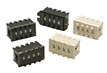
Thumbwheel Switches have circular parts with numbers printed on them. The circular parts can be rotated to select numbers which then form a combination of contact circuit ON/OFF signals. Those switches can convert the numbers to binary,decimal,or hexadecimal numbers and output them.
Features
| Visual Confirmation of Set Values | The selected number is shown as is, so the user can visually confirm the set value to prevent incorrect operation. |
|---|---|
| Retains the Set Value | Code conversion is completely mechanical, so setting values are preserved even when there is no power. |
| Easy Digital Conversion | Code conversion is easily performed for simple circuits and wiring, which in turn improves the reliability and stability of control systems. |
Thumbwheel Switches make code conversion to binary, decimal and hexadecimal easy.
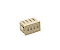
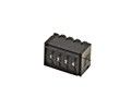
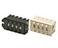
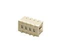
Models
We offer a variety of Thumbwheel Switches in different sizes based on the scale of the device or equipment the switch
will be used in.
They also come in Screw Mounting or Snap-in Mounting models.
We also offer switches with a lock
so that the set value can be locked after it is set, and others that can only be changed with a fine-tipped object,
such as a pen.
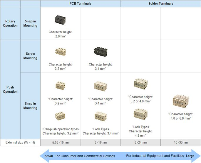
First select the external size that best suits the device or equipment that will house the switch.
Structures
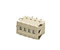
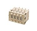
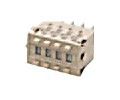
Most of our Thumbwheel Switches consist of a case, pushbutton, wiper, roter, sealing plate, packing, PCB and mounting plate.
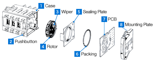
1 Case
The case stores the components of the switch.
The side of the case is designed so that multiple switches can
be easily mounted in sequence.
2 Pushbutton
There are pushbuttons for forward rotation (+) and reverse rotation (−) to set the numerical value.
Each
button is designed to have a click response when pressed and to smoothly rotate the rotor one step each time it is
pressed.
3 Wiper
The wiper is attached to the rotor and the tip wipes across the PCB as the rotor rotates.
It acts as a moving
contact to turn the switch circuit ON and OFF as it comes in contact with the conductor pattern on the
PCB.
Gold alloy is used on the tip that comes in contact with the PCB to increase contact reliability.
4 Rotor
The rotor is a circular plate with numbers printed along the outside surface.
It rotates to set the numerical
value.
5 Sealing Plate
The sealing plate is a transparent resin component that prevents the entry of foreign objects.
It also acts as
a cover for the display window.
6 Packing
This is an elastic rubber component.
It is situated between the PCB and seal plate to prevent foreign objects
from entering the contact area between the wiper and the PCB.
7 PCB
Highly corrosion-resistant gold plating is used for the conductor pattern on the PCB to maintain high contact
reliability between it and the wiper.
The pattern is designed to correspond to the rotational angle of the
rotor to perform numerical code conversion.
8 Mounting Plate
A mounting plate is attached to both ends of the switch so that additional switches can be mounted in sequence simply by pushing them into the mounting hole on the mounting plate.
Lineup

Applications
Settings for Industrial Equipment and Machine Tools
- Set conditions required for operation control, such as times, temperatures, or numbers of cycles
- Set upper and lower limit values for processing dimensions on machine tools
Settings Input for Measuring Devices
- Setting measurement conditions, such as frequency, hours, or temperature
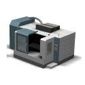
Machine Tools
Semiconductor Manufacturing Equipment
Measuring Devices