Technology of Switches
Actuator Operation & Positions
1. Operation and Positions


1.Terminology
| Classification | Term | Abbreviation | Definition |
|---|---|---|---|
| Force | Operating Force | OF | The force required to press the actuator from the free position to the operating position. |
| Releasing Force | RF | The force required to move the actuator from the total travel position to the releasing position. | |
| Total Travel Force | TTF | The force required to move the actuator from the operating position to the total travel position. | |
| Travel | Pre Travel | PT | The travel distance of the actuator from the free position to the operating position. |
| Over Travel | OT | The travel distance of the actuator from the operating position to the total travel position. | |
| Total Travel | TT | The travel distance of the actuator from the free position to the total travel position. | |
| Movement Differential | MD | The travel distance of the actuator from the operating position to the releasing position. | |
| Position | Free Position | FP | The position of the actuator when not subjected to an external force. |
| Operating Position | OP | The position of the actuator at which the moving contact reverses from the free position when external force is applied. | |
| Releasing Position | RP | The position of the actuator where the movable contact reverses from the operating position to the free position when the external force on the actuator is reduced. | |
| Total Travel Position | TTP | The position of the actuator when it reaches the stopper. |
Operating Characteristics
1. Force-Stroke Characteristics
Operation 1: FP to OP
The actuator is pressed and the switch operates (turns ON) at the operating force (OF).
Operation 2: OP to TTP
The actuator is pressed farther and the switch maintains an ON state.
Operation 3: TTP to RP
The actuator is no longer pressed and when the operating force drops to the release force, the switch releases (turns OFF).
As the operating force (OF) increases, the contact force between the contacts increases and the contact resistance decreases.
2.Contact Resistance - Contact Force Characteristics
The contact resistance varies with the contact force on the contacts.
As the contact force increases, the contact resistance decreases, creating stability between the contacts.
3.Contact Force-Stroke Characteristics
Mechanical Characteristics
The mechanical characteristics are the characteristics when there is no current flowing through the contacts.

Electrical Characteristics
The electrical characteristics are the characteristics when there is current flowing through the contacts.

Snap-Action Mechanism in Electrical Switches
With a snap-action mechanism, the contacts will instantaneously switch at a specific stroke position without relation to the switch operating speed or operating force.
As opposed to a snap-action mechanism, with a slow-action mechanism, the operating speed of the switch is always the travel speed of the contacts.
1. Principles of snap-action mechanisms in electrical switches
If you press down on the top of a sheet of plastic that is bent info an arc, the sheet will suddenly reverse to a U shape at a certain point. This is like a snap-action mechanism.
2. Features of snap-action mechanisms in electrical switches
- Because the contacts switch at high speed, any arc between the contacts will not continue for a long period of time. This reduces contact wear and maintains contact reliability.
- Even miniature switches can make and break large currents.
- With AC, the current flow alternates, so arcs are cut off more easily at the same voltage and current in comparison with DC. Therefore, contact damage is less with AC.
When pressure is applied to the pushbutton of a switch, the force of the movable spring causes the moving contact to quickly switch from the NC fixed contact to the NO fixed contact.
When pressure is released from the pushbutton of a switch, the force of the movable spring causes the moving contact to quickly switch from the NO fixed contact to the NC fixed contact.
Contact Switching Time
If the operating speed is too high, bouncing time increases. This causes repeated switching with minute contact gaps, which in turn increases contact wear due to arcing.
Resin Materials
Resin materials that provide insulation and mechanical strength are used for the cases and covers that protect the internal mechanisms of switches.
| Material name | Material symbol | Characteristics |
|---|---|---|
| Phenol Resin | PF | A thermosetting resin. It provides superior resistance to combustion and tracking. |
| Polybutyrene terephthalate Resin | PBT | A thermoplastic resin. A type of this resin that is reinforced with fiberglass is used for basic switches. |
| Polyamide (nylon) Resin | PA |
A thermoplastic resin. This type of resin has high heat resistance. It slides well and absorbs water well. |
| Polyphenylene sulfide Resin | PPS |
A thermoplastic resin. It provides better resistance to heat than PA. It is used when heat resistance is required, e.g., for soldering. |
Materials are divided into two types:Thermosetting resin and thermoplastic resin.
- Thermosetting resin: These resins harden when heat is applied to them. They cannot be reused.
- Thermoplastic resin: These resins melt when heat is applied to them. They can be reformed to recycle the materials.
Cases and covers are mainly made from PBT and other thermoplastic resins so that the materials can be recycled.
Ingress Protection
Ingress protection tells how much the structure of the Switch provides protection against solid objects and water.
1. First Digit: Protection against Solid Objects
| Code | Level of protection | |
|---|---|---|
| 0 |

|
No protection against entry of dust or dirt. |
| 1 |

|
Round test object with 50-mm diameter will only partially enter the interior. |
| 2 |

|
Round test object with 12.5-mm diameter will only partially enter the interior. |
| 3 |

|
Round test object with 2.5-mm diameter will not enter the interior. |
| 4 |

|
Test object with 1.0-mm diameter will not enter the interior. |
| 5 |

|
No dust or dirt that would affect the correct operation of the device or safety will enter the interior. |
| 6 |

|
Dust and dirt will not enter the interior. |
2. Second Digit: Protection against Liquids
| Code | Level of protection |
Test method outline (test performed using pure water) |
||
|---|---|---|---|---|
| 0 | No protection | No protection against entry of water | No test | |
| 1 |
Protection against water drops
|
No harmful effects from vertical water drips | By using water drip tool vertically and dropping water for 10 min |

|
| 2 |
Protection against water drops
|
No harmful effects of water drips from vertical direction when the enclosure is tilted at 15° from its normal position | By using water drip tool, moving it at an angle of 15°, and dripping water for 10 min (2.5 min per direction) |

|
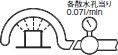
| 3 |
Protection against water spray
|
No harmful effects of water spray at any angle up to 60° from the vertical direction | By using the tool shown on the right, and spraying water vertically at angles up to 60° for 10 min |
|
| 4 |
Protection against water splash 
|
No harmful effects of water splash from all directions | By using the tool shown at the right, and splashing water from all directions for 10 min |

|
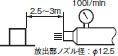
| 5 |
Protection against water jets 
|
No harmful effects of water jets from all directions | By using the tool shown on the right, and jetting the water from all directions to the object surfaces for 1 m2/min, for at least 3 min total. |

|
| 6 |
Protection from strong water jet 
|
No harmful effects of strong water jets from all directions | By using the tool shown on the right, and jetting the water from all directions to the object surfaces for 1 m2/min, for at least 3 min total. |
|
| 7 |
Protection against submersion in water 
|
No harmful effects from submersion in water to a certain level of pressure and length of time | Submerge to 1 m depth in water (when device height is 850 mm or less) for 30 min |

|
This does not imply that the device can be operated under water.
Standard switches are often IP40. Sealed switches are often IP67.
Click here for the switch product lineup