Built-In Color Sensor B5WC

Table of Contents
Summary
As labor shortages become more apparent, there is a growing need for automation through remote monitoring and more
efficient maintenance in the manufacturing industry and multi-functional equipment in the service industry.
Incorporating OMRON's "Color Sensors" into equipment can help solve these problems.
For example, in the case of machine tools, progressive deterioration of lubricant leads to equipment failure. It
will become possible to efficiently maintain the equipment and gauge the optimal time to replace the lubricant by
monitoring the color of the lubricant with a color sensor.
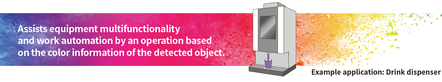
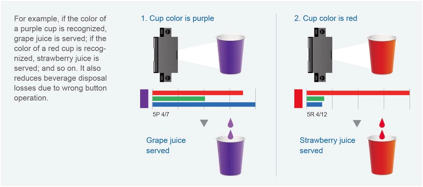
In the case of commercial drink dispensers, color sensors can automate beverage selection according to cup color,
contributing to improved store work efficiency and reduced waste loss due to improper operation of buttons. For
more information, please watch the video
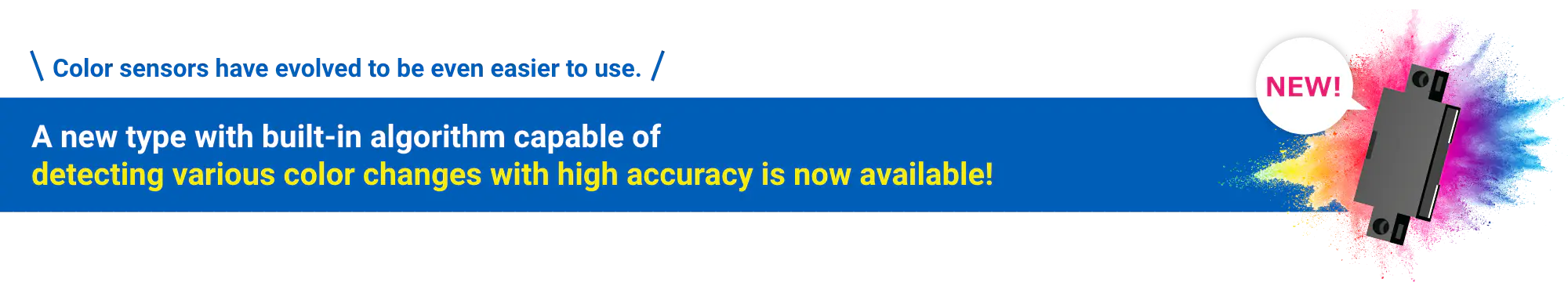
We have released a new type with a built-in algorithm for even easier use.
A sensor with a built-in
algorithm eliminates the need to consider complex algorithms, contributing to a significant reduction in
development time.
Proposal of Color Sensor Utilization
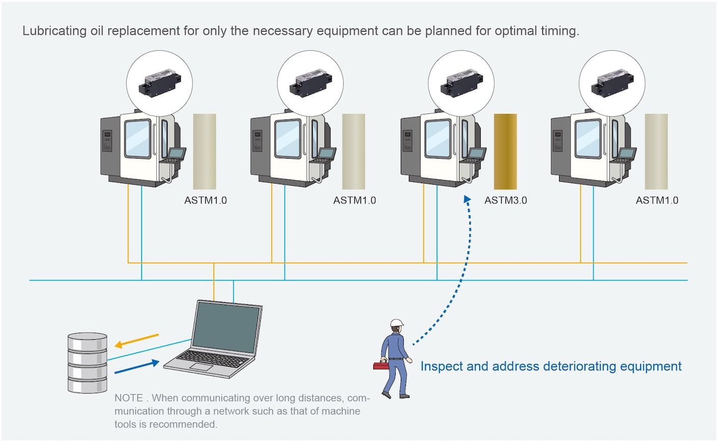
1.Liquid condition monitoring

Challenge (A): Difficult to control oil deterioration
Deterioration of lubricating oil can cause equipment failure. If the timing of replacement is delayed due to the personal judgment criteria of each person in charge or the frequency of inspections, there is a risk of sudden breakdown or destruction of the equipment, which may result in loss of production for a certain period of time.
 Color sensor’s Solution (A): The color sensor informs you of the optimal replacement timing!
By monitoring changes in color with the color sensor, it is possible to quantitatively grasp the degree
of deterioration of the lubricant for each piece of equipment. This eliminates variations in judgment of
deterioration caused by personal visual inspection, allowing lubricant replacement at the optimal
time.
Moreover, by using the built-in algorithm type, there is no need for the customer to create and
incorporate an identification judgment program from scratch. By simply attaching the color sensor to your
equipment, you can easily and instantly receive notification of the optimal replacement timing.
Ratio of RGB output voltage to petroleum product color standard sample* (B5WC-VB2323-1)

Using the petroleum product color standard sample*, the output voltage values of the color sensor were
graphed as a ratio of green and blue to red.
* For ASTM color
The actual measurement of the lubricant with the color sensor can be seen in the video below.
Challenge (B): Variations in deterioration due to frequency of use increases management man-hours
Lubricating oil degradation differs for each equipment depending on operating conditions, making the oil replacement complicated and increasing man-hours required for management.

Color sensor’s Solution (B): No inspection required for all models! The color sensor makes remote management easy.
Color sensors can be used for remote monitoring. The deterioration of lubricating oil in each equipment can be monitored by color, contributing to optimization of oil replacement timing and efficiency.
2.Multi-functionalization of equipment
Challenge: The presence or absence of an object can be detected, but the type of object cannot be identified
Presence/absence detection sensors can detect presence/absence, but cannot output signals according to type.
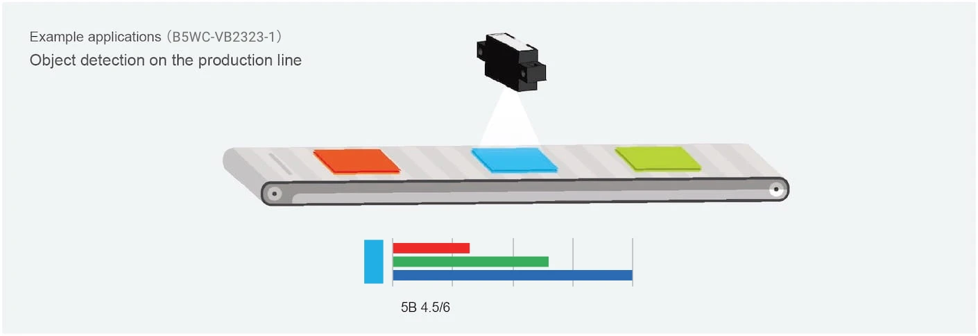
Color sensor’s Solution: The color sensor outputs a signal according to the type of color to identify the type of object.
By color coding the equipment operation with signal output corresponding to the color of the color sensor, it is possible to build multi-functional equipment that meets diversifying needs.
For B5WC-VB2323-1
Ratio of RGB output voltage to Munsell color (B5WC-VB2323-1)
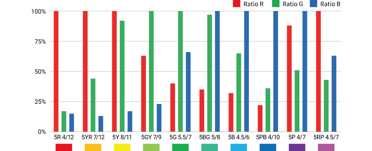
Using Munsell color, the maximum output voltage value of the color sensor was set as 100%, and the ratio of each voltage value to the maximum voltage value was graphed. The ratio of RGB data changes according to the Munsell color.
The actual measurement of color with the color sensor can be seen in the video below.
3.Stable operation of equipment

Challenge: The presence or absence of an object can be detected, but the type of object cannot be identified
In the case of conventional optical sensors, which detect the difference in the amount of reflected light, backgrounds may be detected or the object may not be stably detected due to the background.
Color sensor’s Solution: The color sensor outputs a signal according to the type of color to identify the type of object.
The presence or absence of an object to detect may be confirmed by using a signal output from a color sensor for each color of the detected object.
The measurement with a general optical sensor and the color sensor can be seen in the video below.
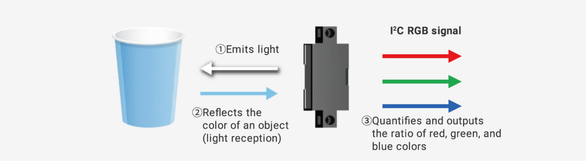
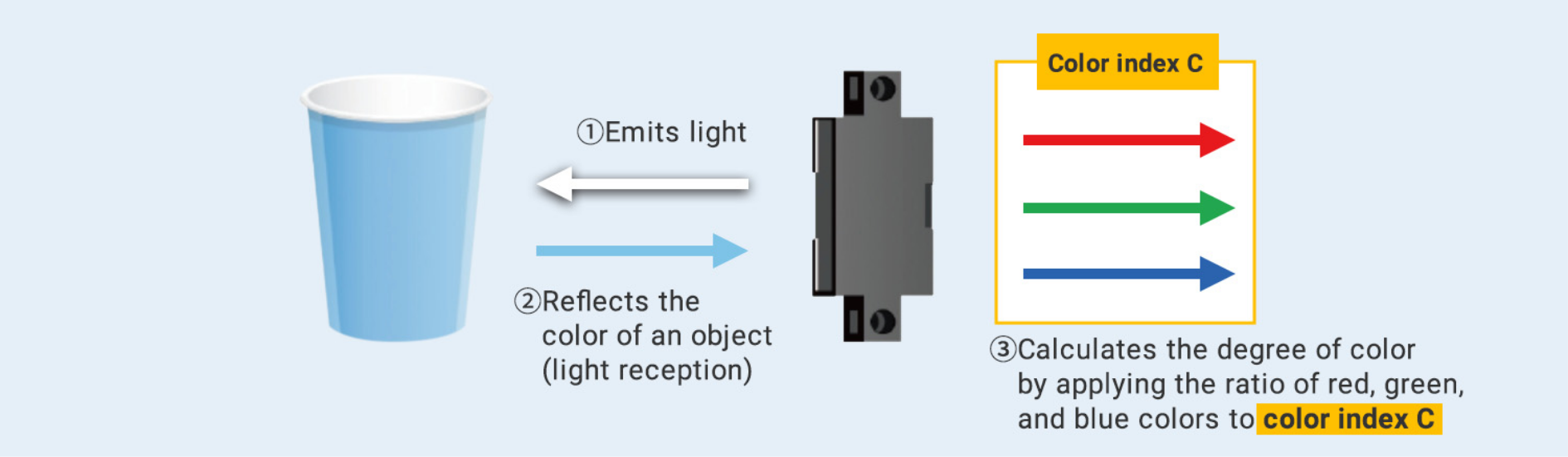
Operating principle of color sensor
A color sensor uses a white LED as its light source to emit light and receive reflected light (the ratio of red, green, and blue is unique to each color) determined by the color of the detected object. The color sensor separates the reflected light received into red, green, and blue, and outputs the red, green, and blue data (RGB data) as voltage values using the I2C communication method.
Operating principle of color sensor
Differences between object and liquid color detection methods
Object color detection
Various colors of light can be produced by combining the “three primary colors of light”: red, green, and blue.
The colors we see with our eyes are the colors of light reflected by objects. For example, an apple appears red
because it reflects red light.
Using red and yellow cups as examples, this section explains color
discrimination.
The ratio of red, green, and blue (RGB ratio) varies with color.
When the color sensor
emits light from white LED light to a red cup, the red light is reflected, and the color sensor receives the red
light. The color sensor separates light into red, green, and blue, and outputs the three colors as voltage
values.
Similarly, when detecting a yellow cup, the color sensor receives yellow light and outputs red,
green, and blue as voltage values.
The graph below shows the result of converting the voltage output of the
color sensor from the red and yellow cups to RGB ratios using an external microcontroller or similar device.
Example of cup color identification (B5WC-VB2323-1)
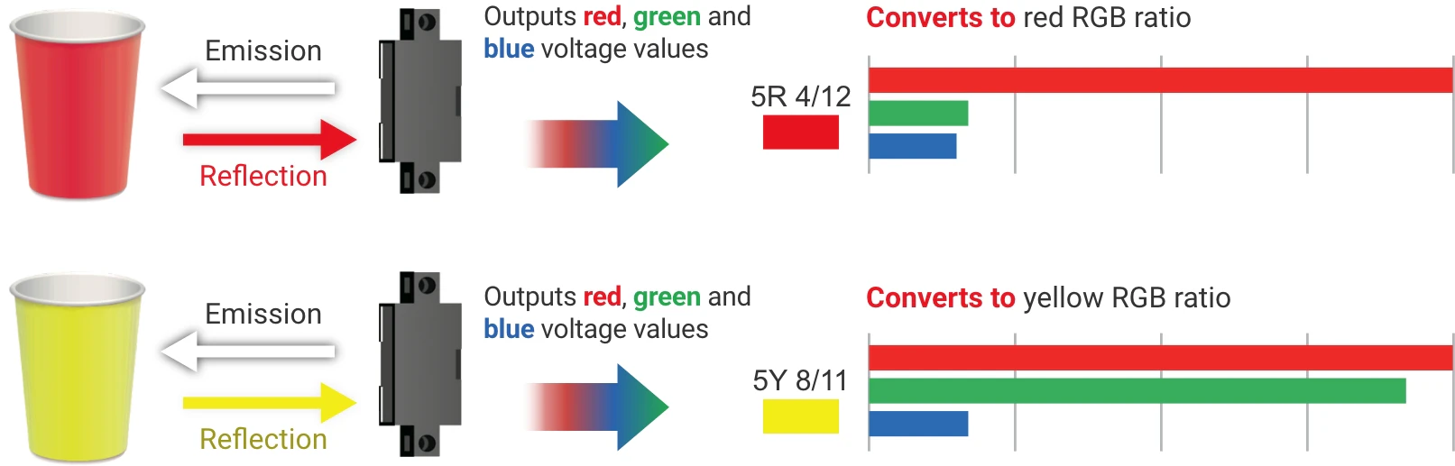
Thus, the difference in the RGB ratio of red and yellow allows us to identify red and yellow cups.
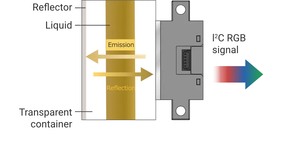
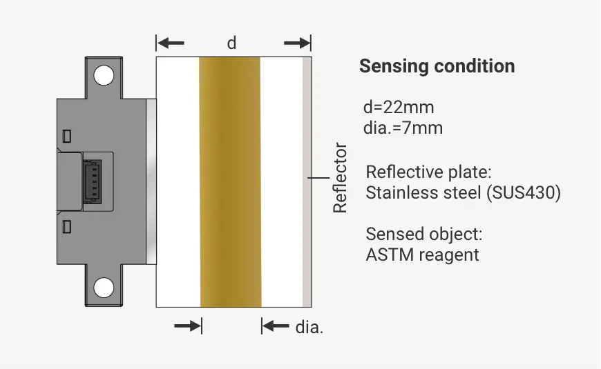
Liquid color detection
When detecting the color of liquid, the light from the color sensor must pass through the liquid.
To detect
the color of liquid in a container, the light from the color sensor is emitted from the transparent part of the
container as shown in the figure, and the light passing through the liquid is reflected by a reflector.
This
reflected light must be received by the color sensor. The reason for passing the light from the color sensor
through the liquid is that the light from the color sensor is not easily affected by the color of the liquid
when reflected from the surface of the liquid or transparent container, so it must always pass through the
liquid so that the white LED of the color sensor changes its RGB ratio according to the color of the liquid.
The use of the color sensor is explained in detail in the user’s manual.

Our conventional model uses a white LED as a light source to emit light and receive to emit light, separates reflected light determined by the color of the detected object into red, green, and blue, and outputs red, green, and blue data (RGB data) as voltage values using the I2C communication method. However, while the output RGB data is highly versatile, customers sometimes do not have enough time to consider the algorithm to determine the color by themselves. In addition to conventional outputs, the newly released color sensor B5WC-VB2323-1 outputs a color judgment index (color index C) calculated using a proprietary algorithm*, thereby helping customers reduce development time. (According to OMRON’s research in August 2024)
Operating principle of built-in algorithm type
Sample code for controlling the B5WC-VB2323-1 is also available for download on GitHub. By using the sample code, you can quickly check and evaluate the basic operation of the color sensor.
 Sample code is now available
 OMRON’s
algorithm is amazing here!
OMRON’s
algorithm is amazing here!
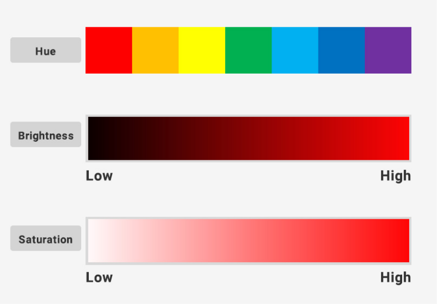
Color has three attributes represented by “hue”, “brightness”, and “saturation”.
“Hue” indicates the type of color, such as red, yellow, green, or blue. “Brightness” indicates the
brightness of the color. The higher the brightness, the more whitish the color; the lower the brightness,
the more blackish the color, but the ratio of the three primary colors of light (red, green, and blue)
does not change. “Saturation” indicates the vividness of the color. The higher the saturation, the more
vivid the color; the lower the saturation, the less vivid the color, and the ratio of the three primary
colors of light changes in proportion to saturation.
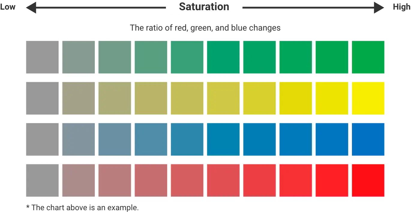
The color index C developed by OMRON calculates color changes as a single index based on the output voltage
value of each RGB obtained from an object in which the ratio of the three primary colors of light changes,
such as saturation.
During operation, the output voltage value of the sensor may be affected by the
external environment such as ambient temperature and power supply voltage. When trying to discriminate subtle
color changes such as saturation, it is necessary to eliminate the influence of output voltage values due to
the external environment in order to accurately discriminate color changes. An algorithm is constructed to
mitigate these external environmental factors, and the color index C is calculated. The color index C ranges
from 0 to 10, with higher saturation resulting in a higher color index C and lower saturation resulting in a
lower color index C.
The color sensor does not miss subtle color changes
For example, as shown in the figure below, by detecting subtle color changes in red, green, and blue, the sensor can detect color differences in similar colors.
Example of color discrimination of red saturation
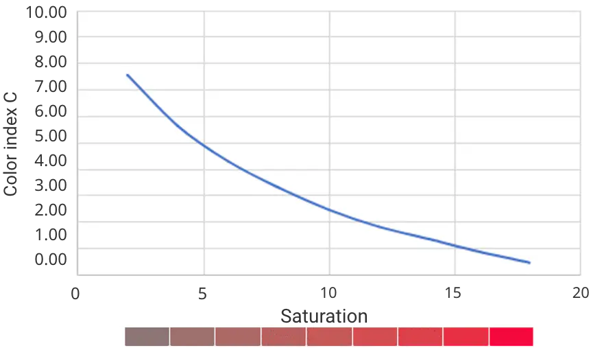
* Theoretically calculated changes in saturation when hue is fixed at 5R and brightness at 5. These are not actual measurement results.
Even slight differences in saturation of the same red color are firmly distinguished by the value of the color index C. The more vivid the red color, the lower the color index C.

 Application example ①:Oil contamination detection
The built-in algorithm alarms you when to change the oil based on the ASTM color!
By
observing the correlation between color index C and ASTM color, which quantify and classify the colors of
petroleum products, it is possible to identify colors in a highly versatile manner.
ASTM color swatches
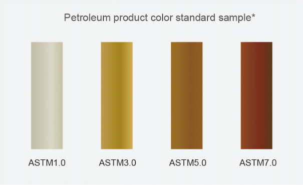
*For ASTM color
The colors shown in the above chart are approximate colors. The way the colors
look depends on the type of computer or monitor you are using.
Most oils have colors with ASTM 0.5 to 1.0 when the oil is new. When the oil degrades, the colors get
darker. egrades, the colors get darker.
The darker the oil color becomes due to oil degradation, the
larger the ASTM color number becomes.The larger the ASTM color number becomes, the lower the color index C
becomes.
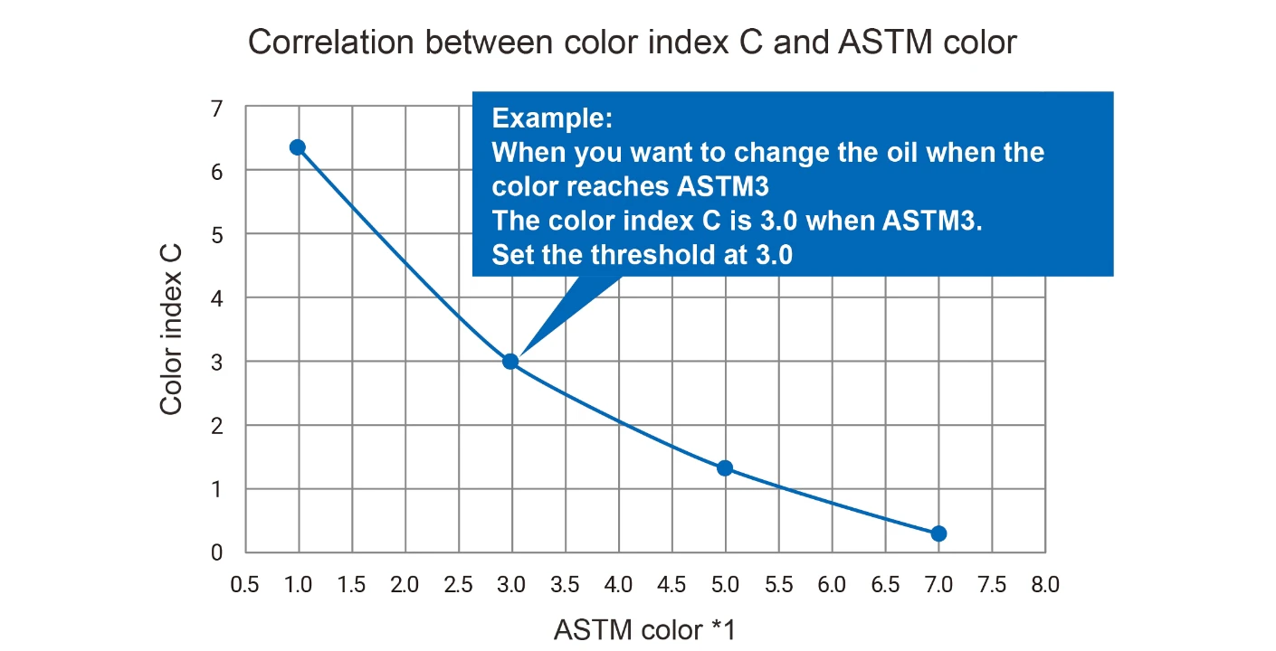
*1 ASTM color is a numerical classification of the color of petroleum products from light (min. 0.5) to dark (max. 8.0) as specified in ASTM D1500.
Note: This data is reference data of the color index C calculated by the output voltage of the color sensor, according to the petroleum product color standard sample. This data is provided for reference only and does not guarantee constant proper operation within this range.
The figure on above shows the correlation between ASTM color and color index C.
For example, set the
color index C, which corresponds to the ASTM color for which you want to replace the oil, as the numerical
value (threshold) of the oil color you want to detect. When the value of the color index C calculated by
the color sensor reaches the set threshold, the oil change timing can be read out via I2C.
Leave it to OMRON to design algorithms for color detection other than
oil!
OMRON possesses the technology to develop color sensors with various algorithms based on the ratio of red, green, and blue.
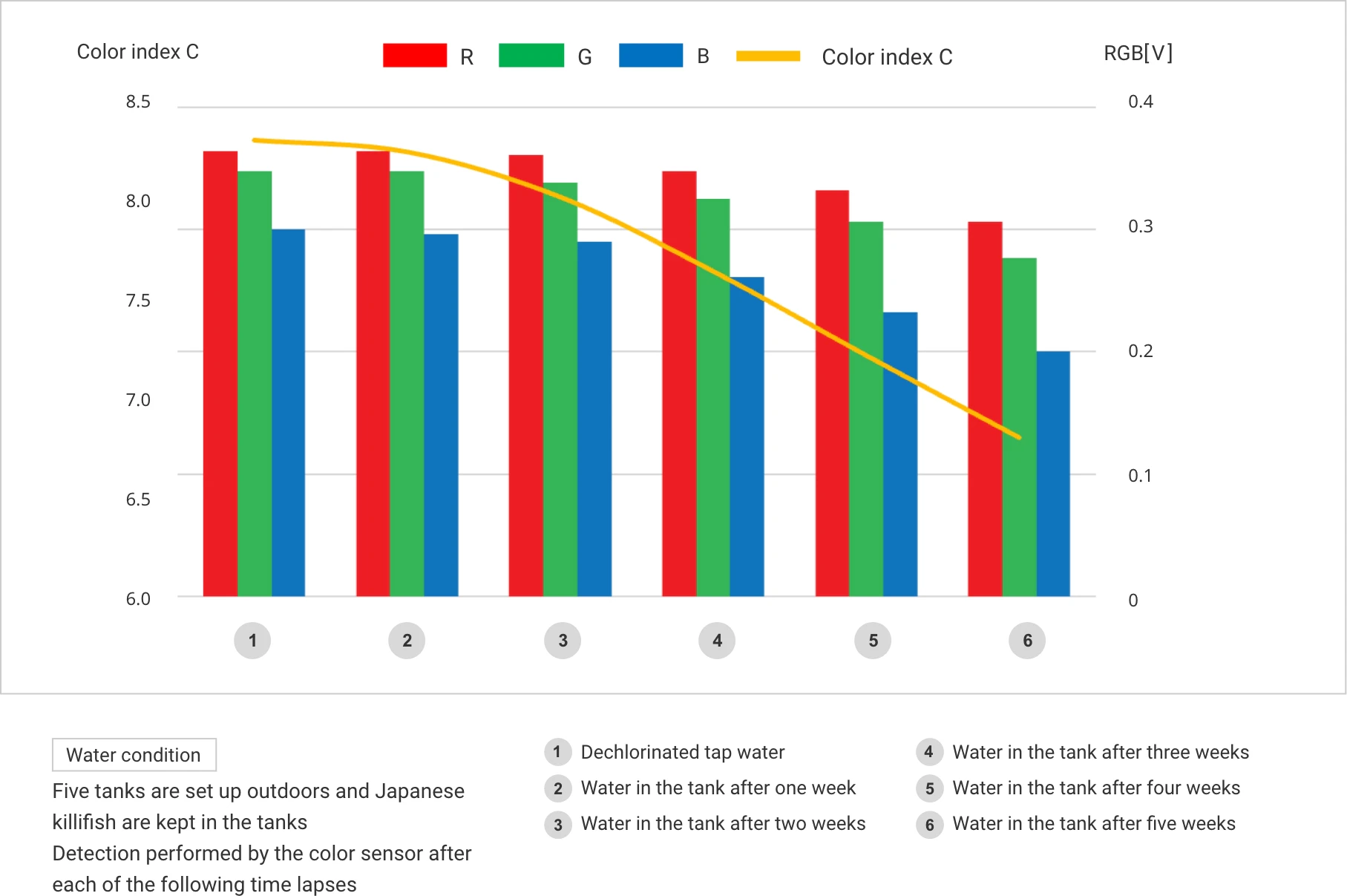
Application example ②:Water contamination detection
The color sensor accurately detects even the slightest change in water color.
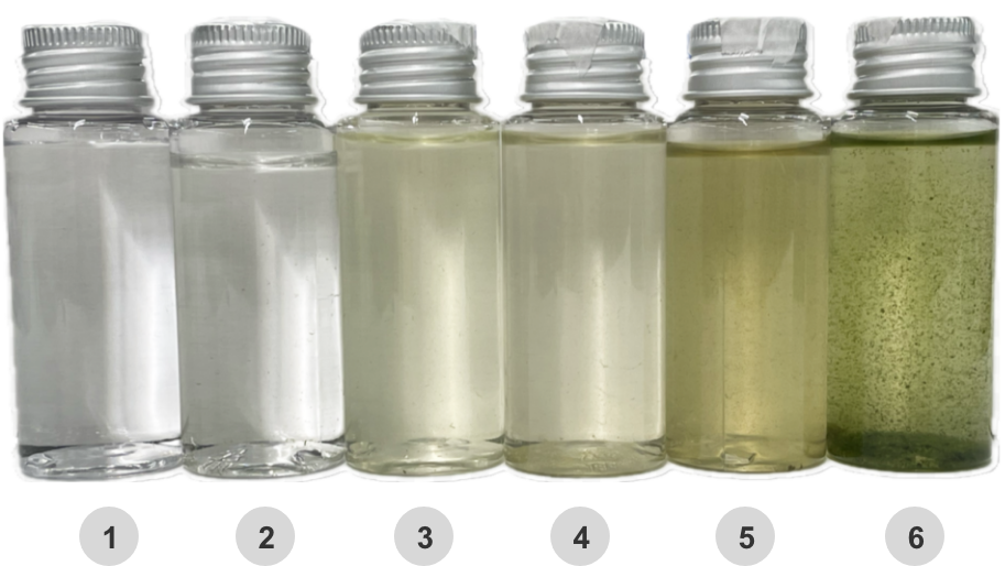
In addition to oil, the color sensor can also identify changes in color with the color index C. For example, the left figure shows the results of using the color sensor to detect changes in the water in a tank of Japanese killifish kept outdoors. Color differences that are difficult to distinguish even visually are clearly identified by the color index C.
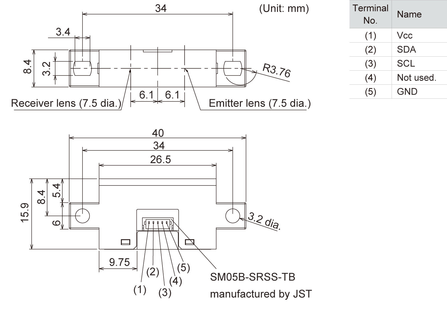
Product Specifications & Dimensions
Product Specifications
| Item |
Model |
B5WC-VB2323-1 (Type with built-in algorithm) |
B5WC-VB2322-1 |
|---|---|---|---|
| Sensing distance | 40mm (white paper) | ||
| Light source | White LED | ||
| Power supply voltage | 5 VDC±5% | ||
| Current consumption | 18 mA max. (at 5.25 VDC) | ||
| Output type | I2C communications supported | ||
| Algorithm | Bulid-in (Color index C output) | --- | |
| I2C output | Output voltage value for red/green/blue: 0.45 V±20% (gray reference plate, when sensing distance is 40 mm) Output saturation voltage: TYP2.75 V (output voltage range: 0 to 2.75V) Color index C: 0.00 to 10.00 SCL/SDA input H voltage: 2.54 to 5.4 V Input L voltage: 0.9 V max., SDA output L voltage:0.44 V max. (at output current of 3 mA) RGB output voltage resolution: 3.2 mV |
Output voltage value for red/green/blue: 0.45 V±20% (gray reference plate, when sensing distance is 40 mm) Output saturation voltage: Typ 2.75 V (output voltage range: 0 to 2.75 V) SCL/SDA input H voltage: 2.54 to 5.4 V Input L voltage: 0.9 V max., SDA output L voltage: 0.44 V max. (at output current of 3 mA) RGB output voltage resolution: 3.2 mV |
|
| Sampling period | 1msec | ||
| Data refresh period | Sampling period (1 msec) x Average count (1 to 50 times) | ||
| Ambient temperature range | Operating: -10 to +70°C, Storage: -25 to +80°C (with no icing or condensation) | ||
Dimensions