Produced in: February 2025

The spread of electric vehicles (EVs) has brought about the rise of EV charger installations in homes, towns, and various other locations as part of charging infrastructure. There are two main charging methods for EVs: AC (alternating current) charging and DC (direct current) charging, with Modes 1 to 3 being AC (normal) charging and Mode 4 being DC (fast) charging. Mode 3 is mainly installed on the walls of homes and commercial buildings, while Mode 4 is installed in commercial buildings as well as highway service areas and public facilities.
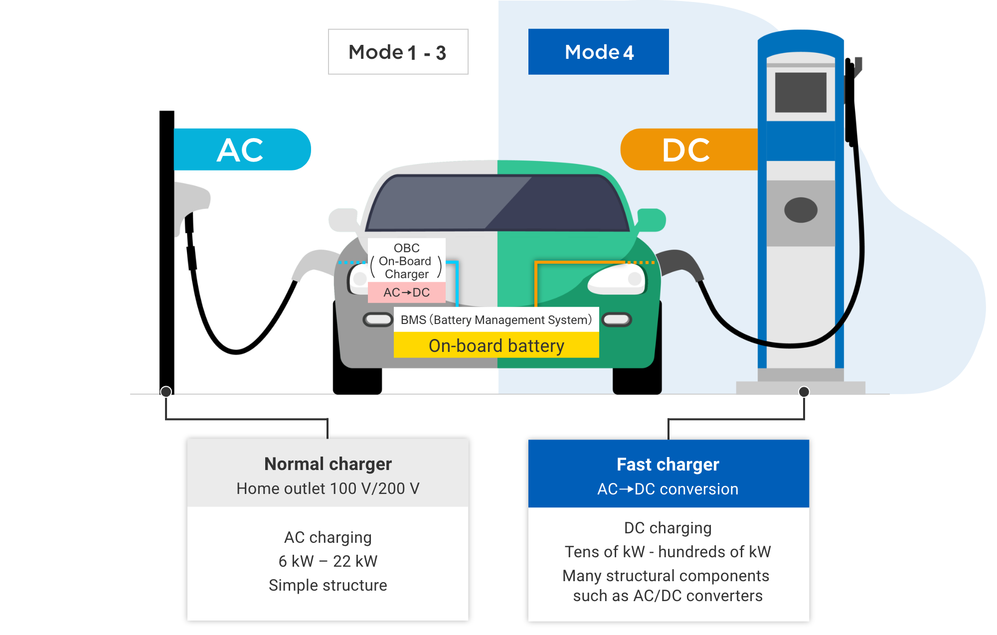
Mode 1 to 3 (normal charger)
Modes 1 to 3 are charging methods that use alternating current (AC) to charge EVs. Since batteries are direct current (DC), however, they must be converted from alternating current (AC) to direct current (DC) for charging. Electric vehicles (EVs) are equipped with a circuit (on-board charger: OBC) that converts
In addition, there is basically one charging port per charger.
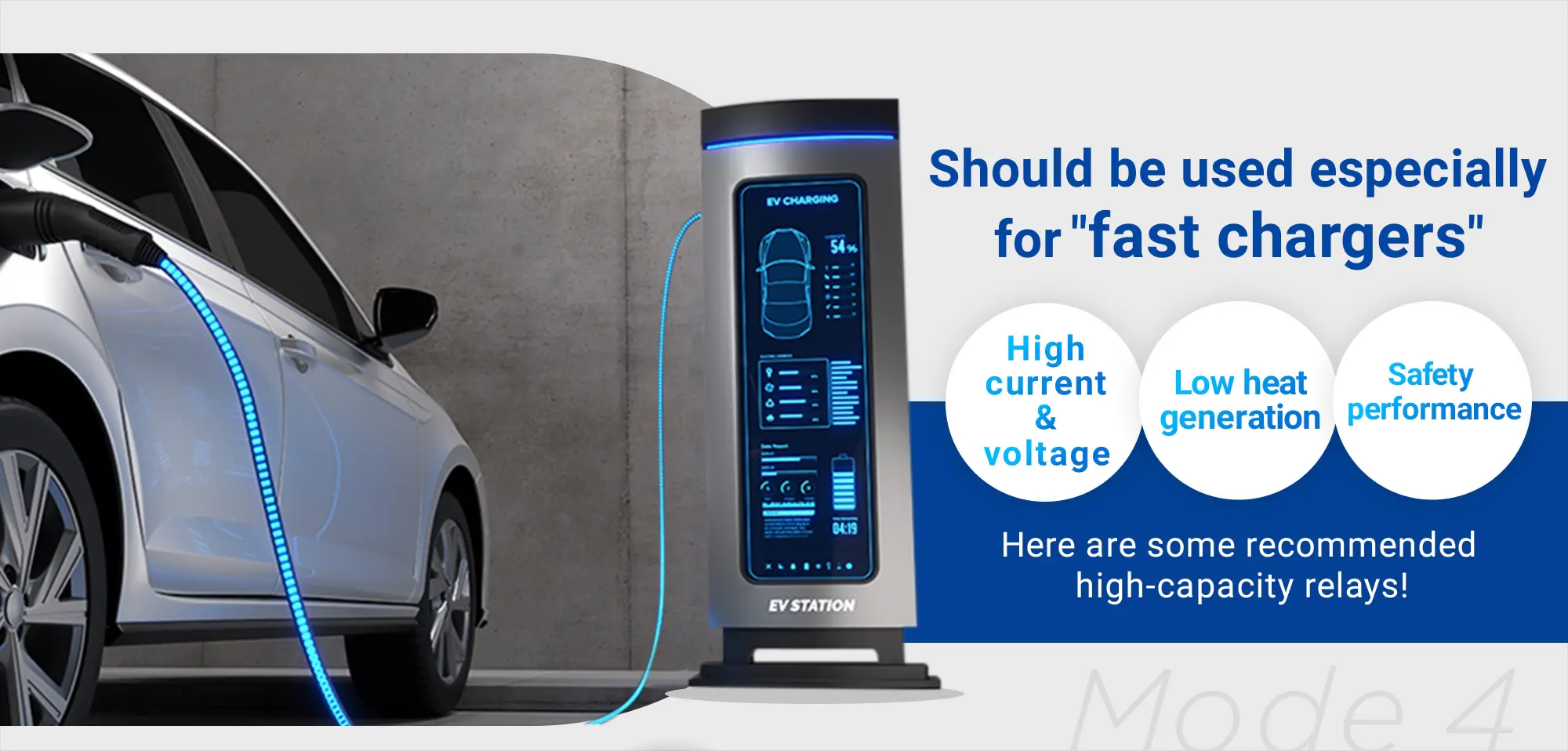
Mode 4 (fast charger)
Mode 4 is a charging method that uses direct current (DC) to charge EVs. Also commonly referred to as fast chargers, they are installed in commercial and public facilities because they handle large amounts of electricity. The received AC power is converted to DC power by a circuit in the charger, and the power is sent directly to the onboard batteries. They can charge the battery with large power ranging from tens of kW to hundreds of kW. In circuits that convert electricity, such as AC-DC, however, conversion losses occur, and losses due to energization also occur, which necessitates components with low resistance. Some chargers installed in public areas have multiple charging ports per charger.
Compared to Mode 3, which has a relatively simple structure, Mode 4, which has a complex structure including transducers, requires different specifications and number of relays for each part. This landing page describes the features of each part of the fast charger circuits and the relays suitable for them.

Mode 4 DC fast chargers are installed in places where fast charging is required, such as highway service areas. We introduce OMRON's relays with high output, low loss (heat generation), and an error detection function (auxiliary contact), which are required for this DC fast charger.
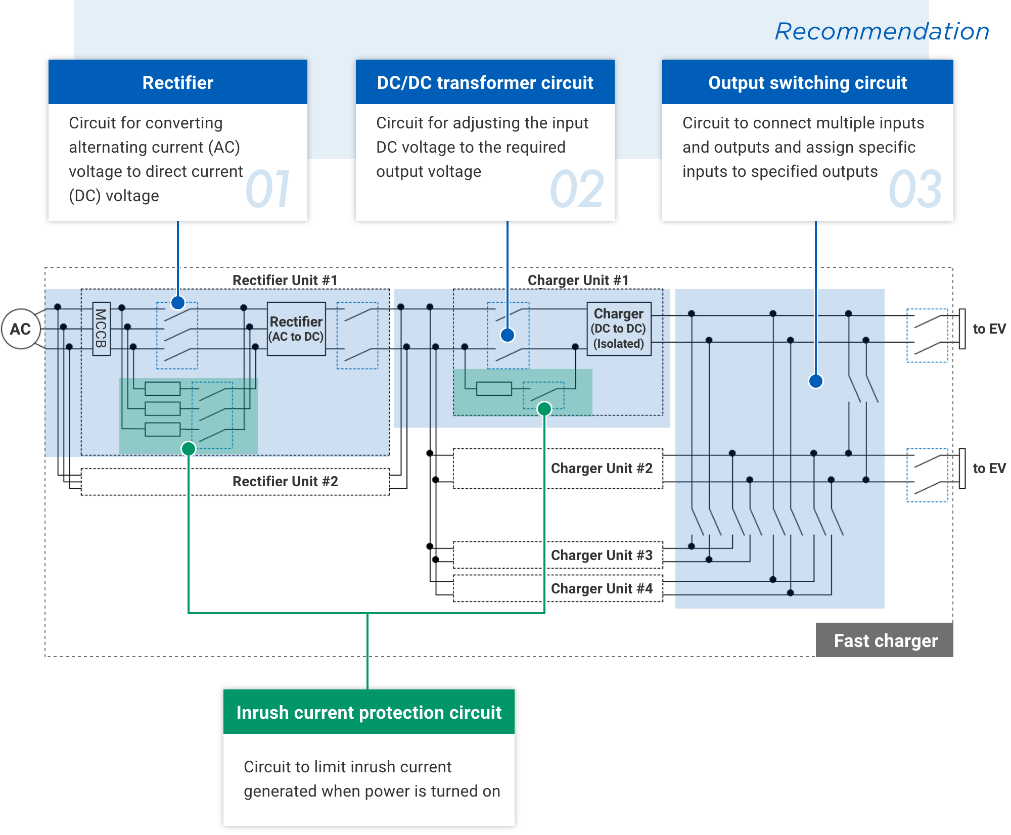

 Switching devices are used to ensure isolation between the primary power system and the secondary side of the rectifier, as well as for emergency power input disconnection. Since the power input is 3-phase, simultaneous opening and closing of three or four poles is required, and multi-pole relays or multiple single-pole relays are used.
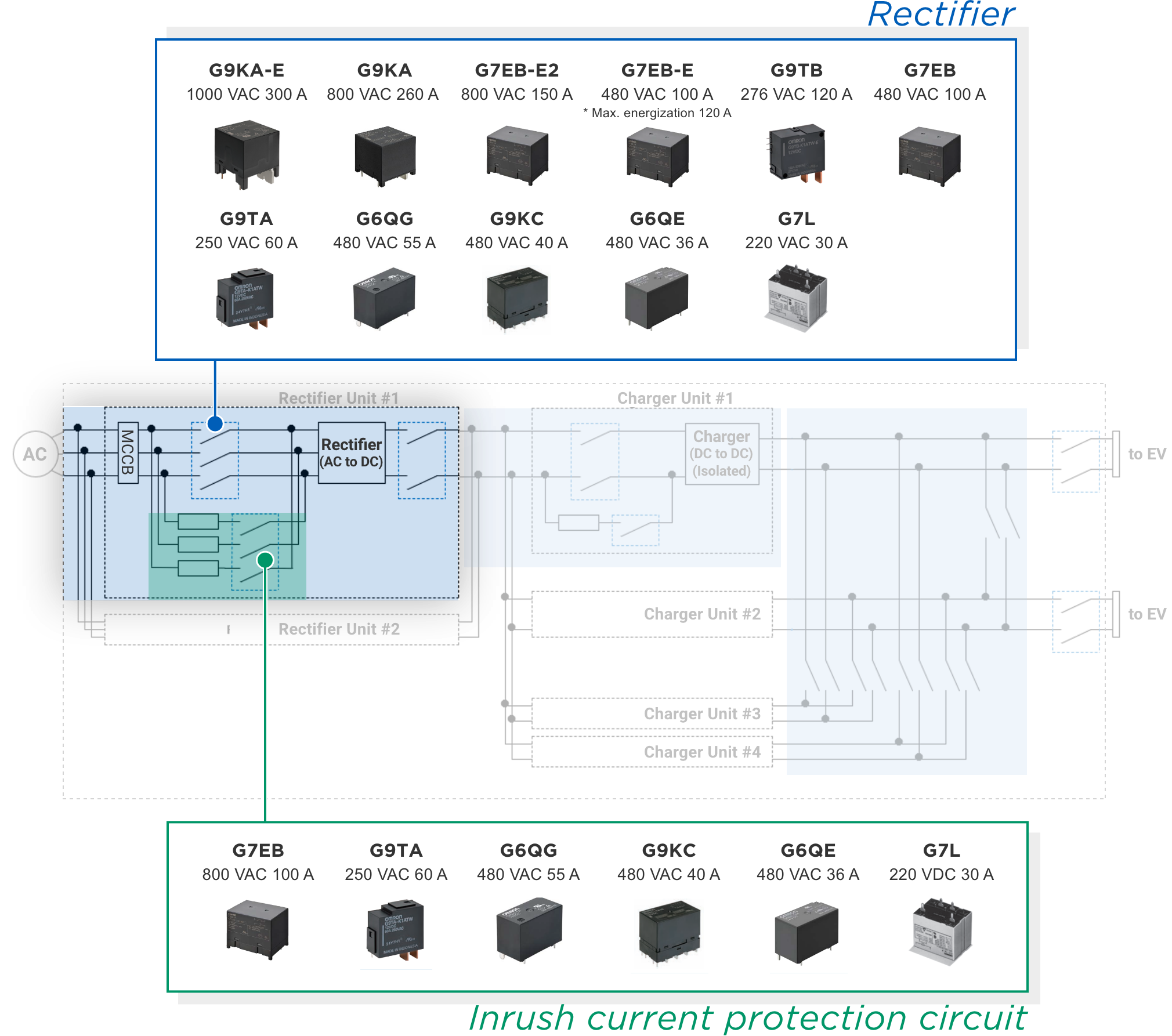
Note. The current and voltage values in the above diagram are the rated values.
 An inrush current prevention circuit may be connected in parallel to the safety cutoff section required on the AC side of the rectifier circuit. Relays capable of turning on and off tens of ampere with voltage rating compatible with grid voltage (200V/400V/690V) are recommended in inrush current protection circuits.
Low heat generation, high voltage, and high current interrupting relay recommended for
| Max. current | Rated voltage |
Aux. contact |
Mounting | Poles/ Latching |
Size (mm)※ | Weight (g) | |
|---|---|---|---|---|---|---|---|
| G9KA-E | 300 A | 1000 VAC | - | PCB mounting | 1-pole | 51x56.7x54.5 | Approx. 235 |
| G9KA | 260 A | 800 VAC | - | PCB mounting | 1-pole | 51x51x47.2 | Approx. 220 |
| G7EB-E2 | 150 A | 800 VAC | - | PCB mounting | 1-pole | 50.5x37x40.5 | Approx. 100 |
| G7EB-E | 120 A | 800 VAC | - | PCB mounting | 1-pole | 50.5x37x40.5 | Approx. 100 |
| G9TB | 120 A | 276 VAC | - | Welding Screw-tightening PCB mounting (under development) |
1-pole Latching |
43.5 x 22.5 x 37.5 (excluding terminals) |
Approx. 70 |
| G7EB | 100 A | 800 VAC | - | PCB mounting | 1-pole | 50.5x37x40.5 | Approx. 100 |
| G9TA | 60 A | 250 VAC | - | Welding Screw-tightening PCB mounting |
1-pole Latching |
39.1 x 18 x 34.5 (excluding terminals) |
Approx. 42 |
| G6QG | 55 A | 480 VAC | - | PCB mounting | 1-pole | 30.5x16x20.5 | Approx. 18 |
| G9KC | 40 A | 480 VAC | PCB mounting | 4-pole | 35.5 x 50.5 x 47.5 | Approx. 220 | |
| G6QE | 36 A | 480 VAC | - | PCB mounting | 1-pole | 30.5 x 16 x 20.5 | Approx. 17 |
| G7L | 30 A | 220 VAC | - | Tab terminal connection Screw-tightening PCB mounting |
1-pole 2-pole |
52.5 x 35.5 x 41 (PCB mounting) |
Approx. 90 - 120 |
Relays recommended for an in rectifier circuits
| Max. input current |
Rated voltage |
Aux. contact |
Mounting | Poles | Size (mm)※ | Weight (g) | |
|---|---|---|---|---|---|---|---|
| G7EB | 100 A | 800 VAC | - | PCB mounting | 1-pole | 50.5x37x40.5 | Approx. 100 |
| G9TA | 60 A | 250 VAC | - | PCB mounting | 1-pole | 39.1 x 18 x 34.5 (excluding terminals) |
Approx. 42 |
| G6QG | 55 A | 480 VAC | - | PCB mounting | 1-pole | 30.5x16x20.5 | Approx. 18 |
| G9KC | 40 A | 480 VAC | PCB mounting | 4-pole | 35.5 x 50.5 x 47.5 | Approx. 220 | |
| G6QE | 36 A | 480 VAC | - | PCB mounting | 1-pole | 30.5 x 16 x 20.5 | Approx. 17 |
| G7L | 30 A | 220 VAC | - | Welding Screw-tightening PCB mounting |
1-pole 2-pole |
52.5 x 35.5 x 41 (PCB mounting) |
Approx. 90 - 120 |
Note. The above specifications are current as of January 2025. Be sure to check the data sheet of each product for details.
Refer to PCB Relays Common Precautions for general precautions.
* Sizes are listed in the order of length x width x height.

 Switching devices may be used in the DC/DC transformer circuit to ensure safety in the event of a malfunction in the charge control circuit. As EV batteries adopt higher voltage, relays capable of switching high voltages (up to 1500 VDC) are required. In addition, to increase charger redundancy, multiple DC/DC transformer circuits are often configured in parallel. Each transformer circuit requires the installation of a relay in the same manner as above.
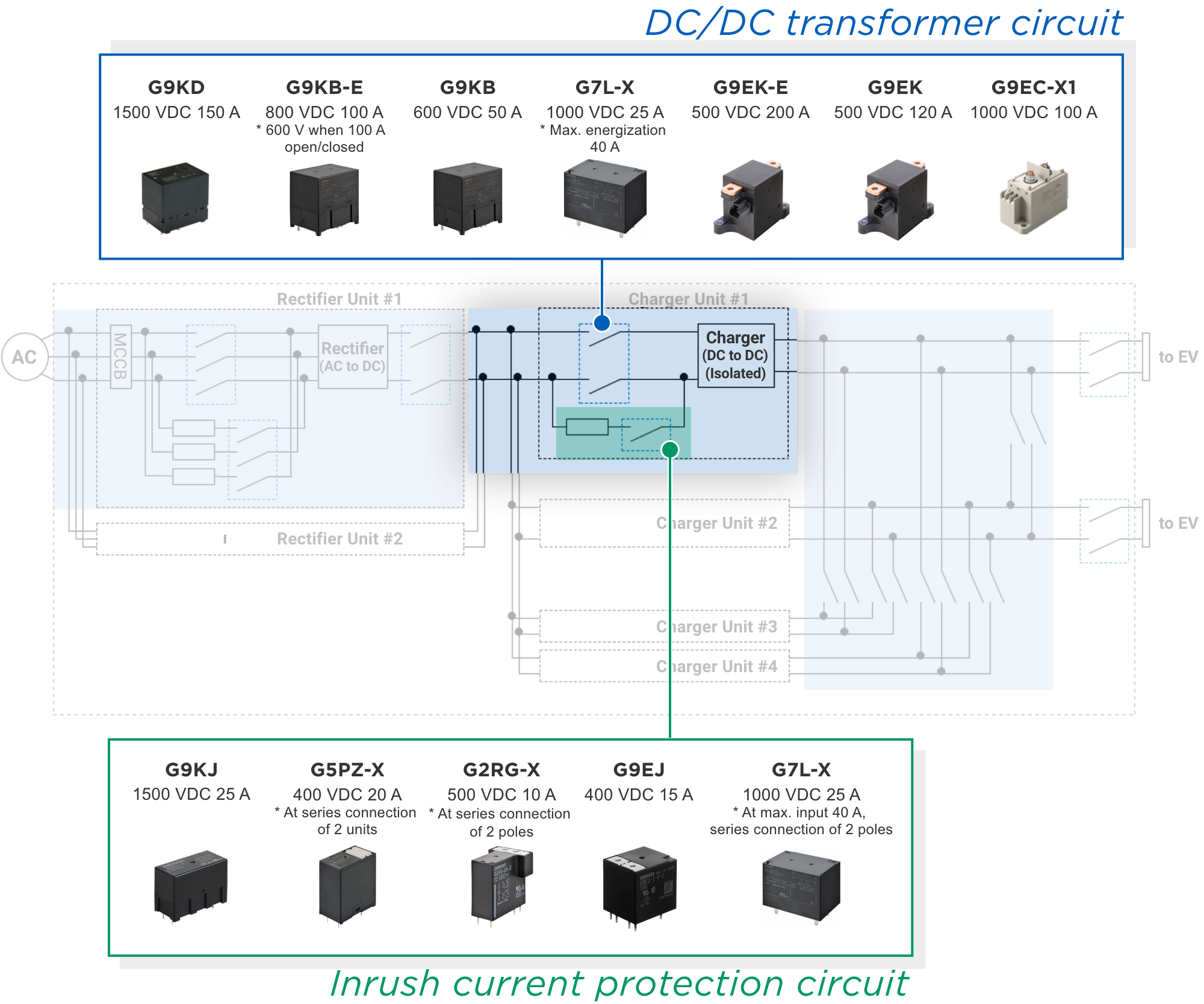
Note. The current and voltage values in the above diagram are the rated values.
An inrush current protection circuit is connected in parallel to this switching device. An inrush current protection circuit is a circuit that prevents the failure of energized electronic components due to the large current caused by charging capacitors when the power is turned on. It consists of a current-limiting resistor and a switching device connected in series to suppress large currents at power-on. Relays capable of turning on and off tens of ampere are recommended for switching devices used in inrush current protection circuits.
Low heat generation, high voltage, and high current interrupting relay recommended for
| Max. current | Rated voltage |
Aux. contact |
Mounting | Poles | Size (mm)※ | Weight (g) | |
|---|---|---|---|---|---|---|---|
| G9EC-X1 | 200 A | 1000 VDC | - | Screw-tightening | 1-pole | 98 x 44 x 86.7 | Approx. 650 |
| G9EK-E | 200 A | 500 VDC | - | Screw-tightening | 1-pole | 86 x 47.7 x 64.2 | Approx. 310 |
| G9KD | 150 A | 1500 VDC | 1b | PCB mounting | 1-pole | 60 x 43 x 56 | Approx. 265 |
| G9EK | 120 A | 500 VDC | - | Screw-tightening | 1-pole | 86 x 47.7 x 64.2 | Approx. 310 - 340 |
| G9KB-E | 100 A | 800 VDC | - | PCB mounting | 1-pole | 50.5x37x50.5 | Approx. 110 |
| G9KB | 50 A | 600 VDC | - | PCB mounting | 1-pole | 50.5x37x50.5 | Approx. 110 |
| G7L-X | 35 A | 1000 VDC (series connection of 2 poles) |
- | PCB mounting | 2-pole | 52.5 x 35.5 x 41 | Approx. 100 |
 for DC/DC transformer circuits
| Max. input current |
Rated voltage |
Mounting | Poles | Size (mm)※ | Weight (g) | |
|---|---|---|---|---|---|---|
| G7L-X | 40 A | 1000 VDC (series connection of 2 poles) |
PCB mounting | 2-pole | 52.5 x 35.5 x 41 | Approx. 100 |
| G9KJ | 25 A | 1500 VDC | PCB mounting | 1-pole | 37.2 x 17 x 25.5 | Approx. 16 |
| G5PZ-X | 20 A | 400 VDC (series connection of 2 units) |
PCB mounting | 1-pole | 26.4x15.2x29.5 | Approx. 15 |
| G2RG-X | 10 A | 500 VDC (series connection of 2 poles) |
PCB mounting | 2-pole | 29 x 23.5 x 29.5 | Approx. 22 |
| G9EJ-E | 15 A | 400 VDC | Tab terminal connection PCB mounting |
1-pole | 31 x 27 x 32.2 (PCB mounting) |
Approx. 45 |
Note. The above specifications are current as of January 2025. Be sure to check the data sheet of each product for details.
Refer to PCB Relays Common Precautions for general precautions.
* Sizes are listed in the order of length x width x height.

 Many fast chargers, which are often installed in public areas such as highway service areas and convenience stores, are capable of charging multiple vehicles with a single charger.
Therefore, the charging output (power) must be controlled according to the charging situation, such as when charging a single car or multiple cars. In addition, to ensure charging capacity in the event of a DC/DC converter failure, the output switching circuit can be switched to resume charging operation.
In the output switching circuit section, AC relays can also be used instead of DC relays, since in principle switching is performed with no load (0 A). Because many relays are used, AC relays, which are smaller, lighter, and less expensive, are increasingly being used rather than DC relays and contactors, which are comparatively more expensive. In addition, by integrating into circuit boards, the number of assembly and connection man-hours can be significantly reduced.
Also, safety standards specify that switching devices comprising output switching circuits be provided with a function to monitor the contact state. For this reason, a relay with auxiliary contacts may be desirable for the part in question.
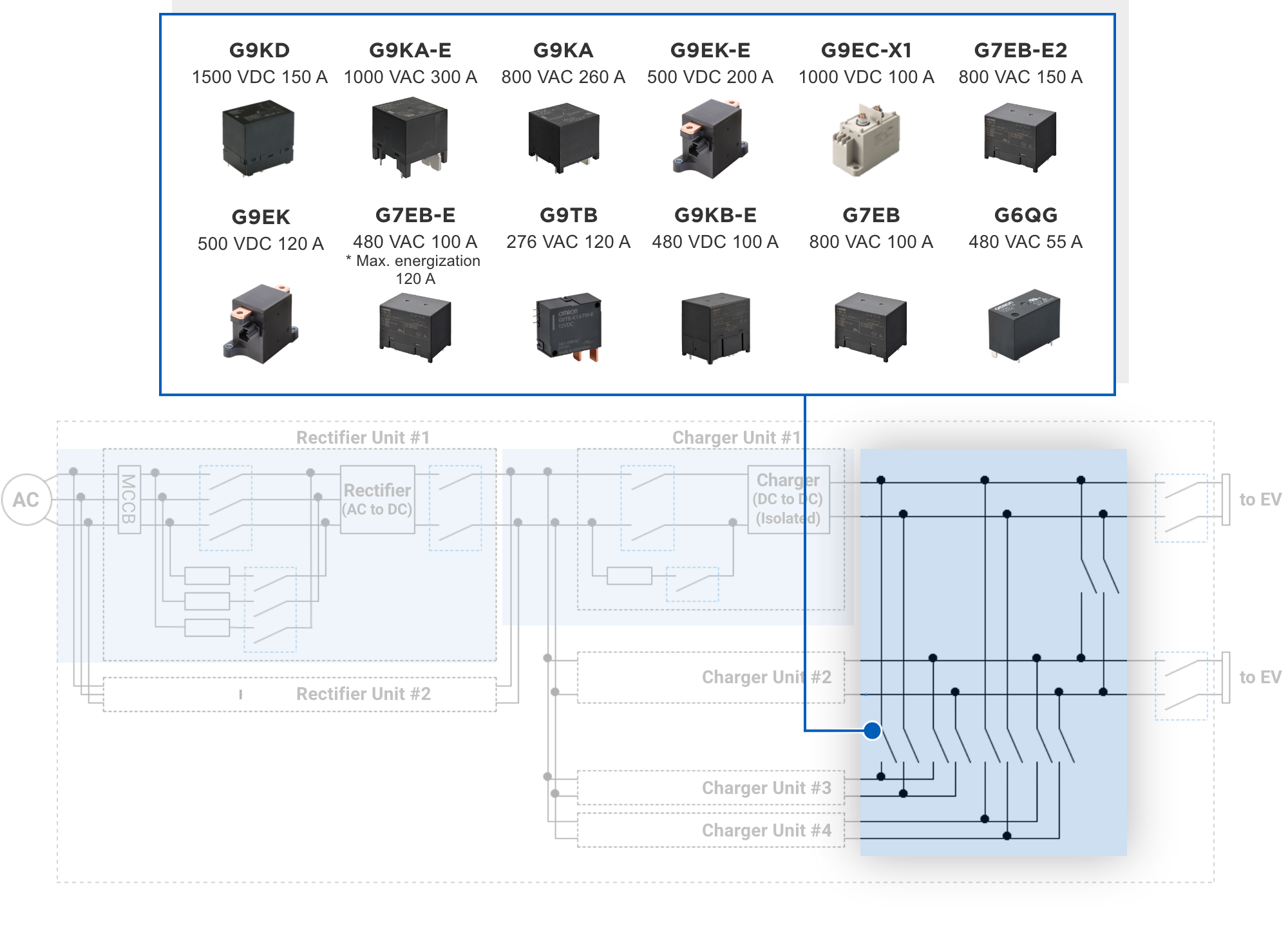
Note. The current and voltage values in the above diagram are the rated values.
Low heat generation, high voltage, and high current interrupting relay recommended for
| Max. current | DC cutoff current |
Rated voltage |
Mounting | Poles/ Latch |
Size (mm)※ | Weight (g) | |
|---|---|---|---|---|---|---|---|
| G9KA-E | 300 A | Limited to no load open/close |
1000 VAC | PCB mounting | 1-pole | 51x56.7x54.5 | Approx. 235 |
| G9KA | 260 A | 200 A at 60 V |
800 VAC | PCB mounting | 1-pole | 51x51x47.2 | Approx. 220 |
| G9EK-E | 200 A | 200 A at 500 V |
500 VDC | Screw-tightening | 1-pole | 47.7 x 86 x 64.2 | Approx. 310 |
| G9EC-X1 | 200 A | 150 A at 1000 V |
1000 VDC | Screw-tightening | 1-pole | 44 x 98 x 86.7 | Approx. 650 |
| G9KD | 150 A | 150 A at 1000 V |
1500 VDC | PCB mounting | 1-pole | 60 x 43 x 56 | Approx. 265 |
| G7EB-E2 | 150 A | 150 A at 60 V |
800 VAC | PCB mounting | 1-pole | 50.5 x 37 x 40.5 | Approx. 100 |
| G9EK | 120 A | 120 A at 500 V |
500 VDC | Screw-tightening | 1-pole | 47.7 x 86 x 64.2 | Approx. 310 - 340 |
| G7EB-E | 120 A | 100 A at 60 V |
800 VAC | PCB mounting | 1-pole | 50.5 x 37 x 40.5 | Approx. 100 |
| G9TB | 120 A | Limited to no load open/close |
276 VAC | Welding Screw-tightening PCB mounting (under development) |
1-pole Latching |
43.5 x 22.5 x 37.5 | Approx. 70 |
| G9KB-E | 100 A | 100 A at 600 V |
800 VDC | PCB mounting | 1-pole | 50.5x37x50.5 | Approx. 110 |
| G7EB | 100 A | 100 A at 60 V |
800 VAC | PCB mounting | 1-pole | 50.5x37x40.5 | Approx. 100 |
| G6QG | 55 A | Limited to no load open/close |
480 VAC | PCB mounting | 1-pole | 30.5x16x20.5 | Approx. 18 |
Note. The above specifications are current as of January 2025. Be sure to check the data sheet of each product for details.
When using relays with no load switching (so-called dry switching), Refer to PCB Relays Common Precautions for general precautions.
* Sizes are listed in the order of length x width x height.