
OMRON relays are used in a wide variety of products by our customers, and there are a wide range of design considerations, such as counter electromotive voltage of coils, holding voltage, and the effects of magnetic fields when DC relays are used. To help you use OMRON relays more comfortably and easily, this page provides easy-to-understand explanations of the most frequently asked questions from our customers.
Please feel free to consult with OMRON's technical members about any "unknowns" regarding power relays.
Contents
- 05. What is the effect of the magnetic field from
permanent magnets in a relay? - 06. Can DC power relays be used with less than 1A?
- 07. Can two relays be connected in series or parallel?
- 08. What happens to a relay when a large current
(short-circuit current) is energized? - 09. What is the contact resistance capability of
high-capacity power relays? - 10. How can I energize a large current with PCBs?

Counter electromotive voltage generated when the coil voltage of a relay is interrupted causes overvoltage to various elements in the circuit, resulting in malfunctions and breakdowns. Thus countermeasures to suppress counter electromotive voltage are necessary.
Diodes are generally used for DC coils, but for some high-capacity relays a combination of a Zener diode as well as a diode is recommended because the contact open/close speed is reduced and the electrical durability is greatly affected.
 What happens if I use only diodes?
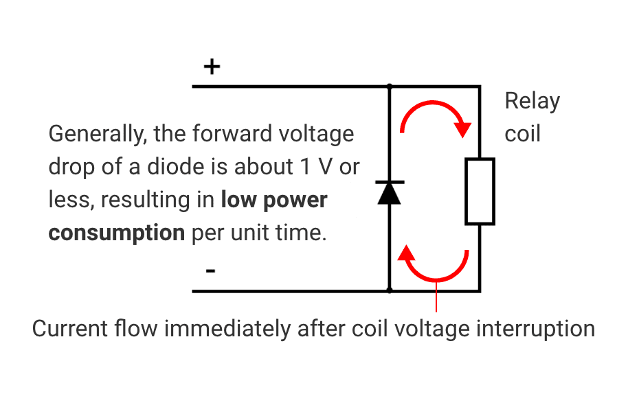
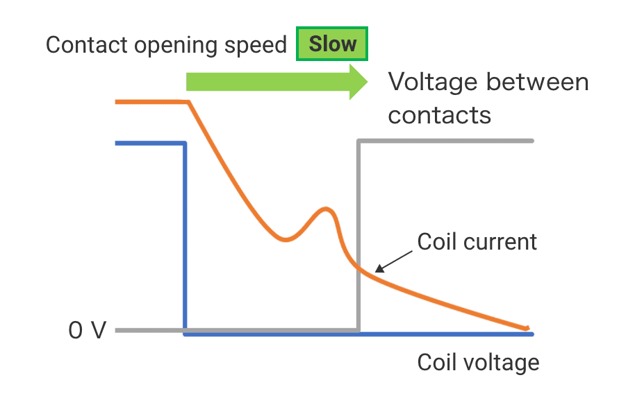
Diodes have a small forward voltage drop, resulting in slower power dissipation speed and longer coil current duration. Since the magnetic force of the coil depends on the coil current, a long coil current decay time slows the speed at which the relay contacts open and close, inducing premature welding failures of the contacts.
Circuit diagram for diode
Waveform for diode
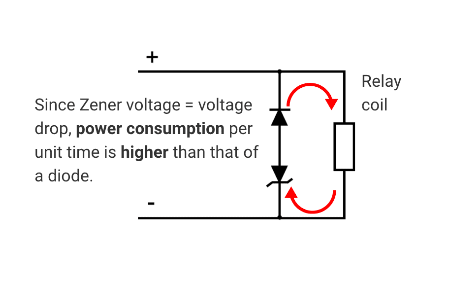
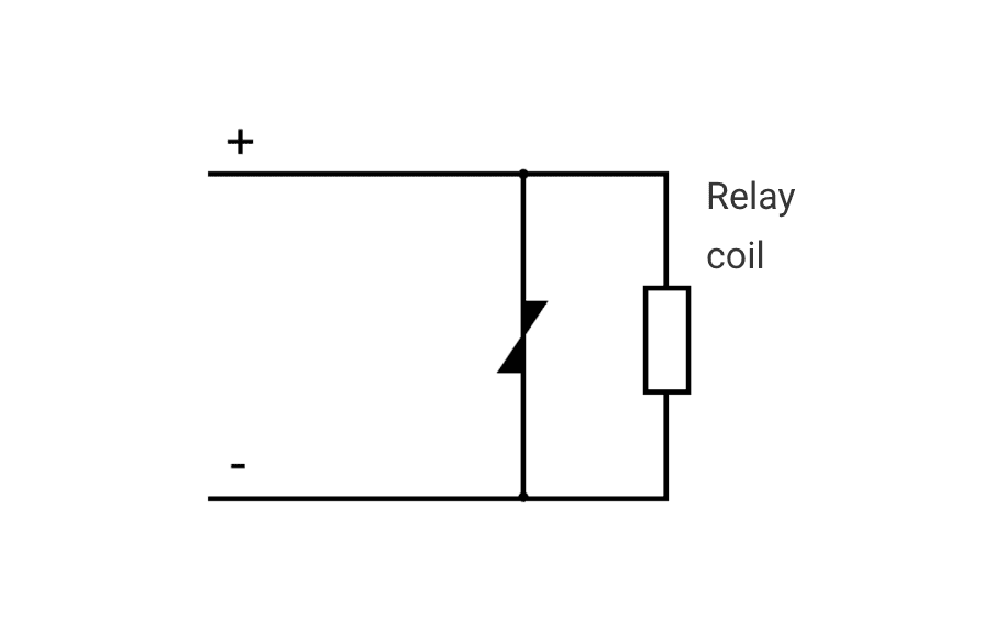
When a Zener diode is connected in series with a diode as shown in the below figure, the large voltage drop of the Zener diode shortens the decay time of the coil current, which increases the opening speed of the relay contacts and prevents failure due to premature welding of the contacts.
Circuit diagram for diode & Zener diode
Waveform for diode & Zener diode
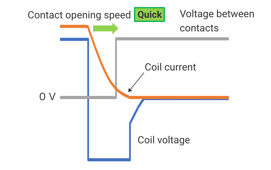
If the Zener voltage is too low, it is less effective in increasing the contact opening speed.
For this reason, select the optimum Zener voltage for each model.
 What is the optimum Zener diode voltage?
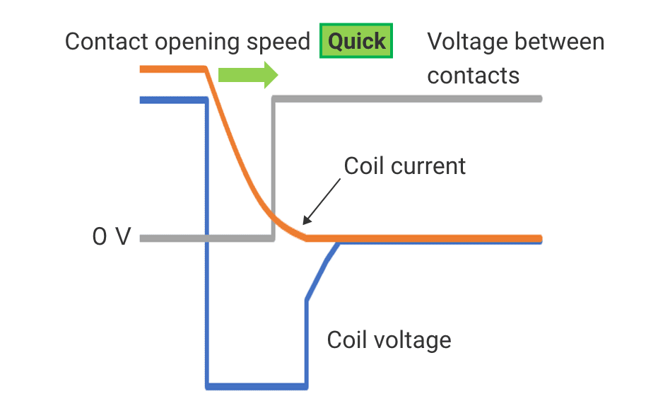
When a Zener diode is connected in series with a diode as shown in the above figure, the large voltage drop of the Zener diode shortens the decay time of the coil current, which increases the opening speed of the relay contacts and prevents failure due to premature welding of the contacts. On the other hand, if the Zener voltage is too low, the contact opening speed will slow down. And if the voltage of the Zener diode is too high, it may adversely affect the peripheral elements.
For this reason, the optimum Zener voltage is set for each model.
| Model | Recommended Zener Voltage * Rated coil voltage ratio |
|---|---|
| G9KA | x2 to 3 |
| G7EB | x3 |
| G9KB | x3 |
| G7L-X | x1 to 2 |
| G2RG-X | x3 |
| G5PZ-X | x1 to 3 |
When used with a Zener diode, the diode should be above the Zener voltage and the forward current should be above the rated current of the coil.
Please refer to the table on the left for the recommended Zener voltage for each model.
 Can't I use varistors for countermeasures against back EMF?
Instead of a combination of diode and Zener diode, a varistor can be used.
In this case, too, the coil current waveform is similar to that of the combination.
Circuit diagram for varistor
The recommended varistor voltage is basically the same as the recommended Zener voltage. If the varistor voltage is smaller than the maximum value of the power supply voltage, however, there is a possibility that voltage will not be correctly applied to the coil. Be sure to select a voltage greater than the maximum power supply voltage.

The coil of a relay consumes a certain amount of power in the ON state (voltage applied). That is, it continues to consume power during operation.
In the case of applications in which it continues to be ON, the power consumption of the coil can be reduced by 50 to 80%*, by lowering the voltage to the holding voltage range after power is applied.
* Depends on the coil specification.
In addition, some high-capacity relays must be used with holding voltage. Refer to Precautions in the datasheet
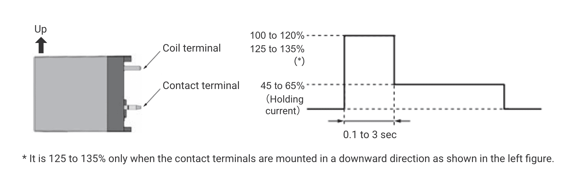
The following steps for applying voltage to the relay coil are required for complete operation of the relay.
- Apply the voltage (rated voltage) required for initial operation of each relay for at least 0.1 second (within the specified time range).
- After Step 1, lower the applied voltage to the holding voltage range.
Note 1: Do not continue to apply the rated voltage for longer than the predetermined time.
Note 2: The voltage application range should not exceed the stated voltage range.
Example of G7EB
Make sure that the setting does not exceed this range due to coil voltage fluctuations, etc.

As explained in "02 How can coil power consumption be reduced?", power consumption can be reduced by using a holding voltage for the coil. In addition, some relays must be used at holding voltage to maintain their rated characteristics. Please check the datasheet of each model for the specified holding voltage value of high capacitance power relays before use.
There are several recommended methods for holding voltage circuits. Below are some of the introductions.
 What is CR method?
The CR system consists of a holding voltage circuit that passes current through a capacitor to operate a relay. The feature of this method is that it is relatively easy to control, as it is automatically shifted to a holding voltage state by simply applying the rated coil voltage to the control circuit as usual. The coil current is reduced by the resistor (R1), resulting in reduced power consumption. Determine the resistance value (R1) so that it meets the holding voltage specification (refer data sheet) for each relay. Note that if the same resistor as the coil resistor is used for R1, the coil current will be halved, and the power consumption of the entire circuit can be halved.
Recommended holding voltage CR circuit example, example of coil voltage and current waveforms in CR circuit and peripheral component selection method
Recommended holding voltage CR circuit example

Example of coil voltage and current waveforms in CR circuit

(1) Apply 100% rated voltage to the coil.
(2) After the relay is turned on by the current flowing through C (capacitor),
The current is suppressed by R (resistance).
Peripheral component selection method
| Symbol | Component | Selection method | Reference Parts *G9KA 12VDC assumed to hold 50% voltage |
|---|---|---|---|
| Q1 | Relay drive transistor |
“Vce” is more than the coil voltage plus ZD voltage. “Ic” is equal to or more than coil rated current. |
P-channel, Vce=50V, Ic=500mA |
| D1 | Surge absorbing diode |
"If" is equal to or more than the rated coil current. "Vr" is 2 to 3 times the coil voltage. |
Reverse voltage Vr=36V, Forward current If=500mA |
| D2 | Zener diode | Zener voltage specified in catalog. Wattage is the shear head surge reverse current (power), greater than or equal to the relay's rated current (power). |
Zener Vz=36V, Pd=1W (Non-repetitive surge: 3~5W acceptable) |
| M1 | Current switching MOS FET |
Select at "Vds" more than the coil voltage plus ZD voltage. Select "Ids" more than the coil current. | N-Channel, Vds=60V, Id= 500mA |
| R1 | Coil current limiting resistor |
Resistance value: Determined according to the holding voltage (%) Power consumption: More than resistance multiplied by the square of the holding current |
Resistance R=28.8Ω, 1.5W |
| R2 | Time constant resistor | When applying the rated voltage to the coil for 100 ms, the time constant C x R should be approximately 70ms to 80ms. Note: Adjust to suit the gate sensitivity and capacitance of the MOS FET. |
Capacitance 30μF, Rated voltage 40VDC |
| C1 | Time constant capacitor | Resistance R=2.5kΩ, 1/4W |
![]()
- The user can simply turn the relay on and off with normal control, and automatically save energy by holding voltage
![]()
- The time required to apply the rated voltage to the coil varies depending on the gate capacitance and sensitivity of the C, R, and MOS-FETs, so appropriate tuning is required at the time of design
 What is switch method? (1)
In the first switching method, a holding voltage circuit can be constructed by simply adding a current-limiting resistor (R1) and a switching element (Q2). After applying the rated voltage to the control circuit, the coil current is reduced by turning off the switch (Q2). If R1 is the same resistance as the coil resistance, the coil current is halved, and the power consumption of the entire circuit can be halved.
Recommended holding voltage circuit example with switch, example of coil voltage and current waveforms in holding circuit with switch and peripheral component selection method
Recommended holding voltage circuit example with switch

Example of coil voltage and current waveforms in holding circuit with switch

(1) Turn on switches Q1 and Q2.
(2) After 100ms~3s, turn off switch Q2.
Peripheral component selection method
| Symbol | Component | Selection method | Reference Parts *G9KA 12VDC assumed to hold 50% voltage |
|---|---|---|---|
| Q1 | Relay drive transistor |
“Vce” is more than the coil voltage plus ZD voltage. “Ic” is equal to or more than coil rated current. |
P-channel, Vce=50V, Ic=500mA |
| D1 | Surge absorbing diode |
"If" is equal to or more than the rated coil current. "Vr" is 2 to 3 times the coil voltage. |
Reverse voltage Vr=36V, Forward current If=500mA |
| D2 | Zener diode | Zener voltage specified in catalog. Wattage is the shear head surge reverse current (power), greater than or equal to the relay's rated current (power). |
Zener Vz=36V, Pd=1W (Non-repetitive surge: 3~5W acceptable) |
| R1 | Coil current limiting resistor |
Resistance value: Determined according to the holding voltage (%) Power consumption: More than resistance multiplied by the square of the holding current |
Resistance R=28.8Ω, 1.5W |
| Q2 | Holding voltage switching transistor | "Vce" is more than the coil voltage plus ZD voltage. "Ic" is equal to or more than coil rated current. |
N-channel, Vce=50V, Ic=500mA |
![]()
- Simple structure that only requires the addition of a switching element for switching between resistance and holding voltage and easy circuit design
- The timing of the transition to holding voltage control can be set arbitrarily by the user
![]()
- The presence of resistor halves power-saving effect
- In addition to the ON/OFF control output of the relay, a control output for the holding voltage is required
 What is switch method? (2)
The second switching method uses two power supplies. If a low voltage (B) for holding the coil can be prepared separately from the rated coil voltage (A), it is possible to switch to the holding voltage by switching with a switch. When switching to 50% voltage, the current is also halved to 50%, so the power consumption of the entire circuit can be greatly reduced to 1/4 of the rated voltage.
Recommended holding voltage circuit example with switch, example of coil voltage and current waveforms in holding circuit with switch and peripheral component selection method
Recommended holding voltage circuit example with switch

Example of coil voltage and current waveforms in holding circuit with switch

(1) Turn on switch Q1 and turn on the coil drive switch.
(2) After 100ms~3s, turn off switch Q1.
Peripheral component selection method
| Symbol | Component | Selection method | Reference Parts *G9KA 12VDC assumed to hold 50% voltage |
|---|---|---|---|
| Q1 | Relay drive transistor |
“Vce” is more than the coil voltage plus ZD voltage. “Ic” is equal to or more than coil rated current. |
P-channel, Vce=50V, Ic=500mA |
| Q2 | Holding current transistor | "Vce" is more than the coil voltage plus ZD voltage. "Ic" is equal to or more than coil rated current. |
N-channel, Vce=50V, Ic=300mA |
| D1 | Backflow prevention diode | "Vr" is more than the rated coil voltage. "If" is more than 50% of the rated coil current. |
Reverse voltage Vr=36V, Forward current If=500mA |
| D2 | Surge absorbing diode |
"If" is equal to or more than the rated coil current. "Vr" is 2 to 3 times the coil voltage. |
Reverse voltage Vr=36V, Forward current If=500mA |
| D3 | Zener diode | Zener voltage specified in catalog. Wattage is the shear head surge reverse current (power), greater than or equal to the relay's rated current (power). |
Zener Vz=36V, Pd=1W (Non-repetitive surge: 3~5W acceptable) |
![]()
- By reducing voltage and current, the power saving effect of the entire circuit can be maximized
![]()
- It can be used only if there is a power supply voltage suitable for the holding voltage other than the relay rated voltage on the circuit
 What is PWM method?
PWM (Pulse Width Modulation) control is a method of controlling power by repeatedly turning it on and off using semiconductors. Fast ON/OFF switching maintains constant voltage with less power.

The more time the voltage is off, the less power is consumed.
By turning more voltage signals on and off per second, it is possible to apply a constant average voltage while increasing the OFF time. This ON/OFF ratio is called duty ratio.
Example of general PWM circuit+Zener diode

* Due to the Zener diode, the PWM circuit may not operate as expected.
We do not recommend the use of PWM control circuits because of the power loss caused by the Zener diode and the difficulty in significantly reducing the duty ratio in general PWM control circuits.
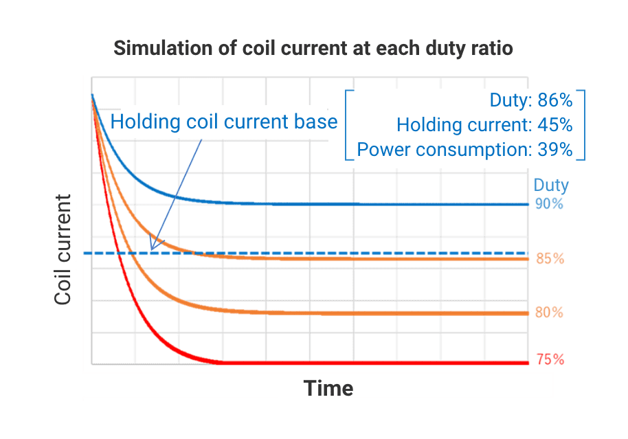
The following are examples of coil current values at various duty ratios for the G9KA power relay type. A typical PWM circuit & Zener diode combination requires a duty ratio of 86% or more to keep the coil current to maintain the relay on. This causes the relay to generate more heat than in the recommended PWM circuit holding state because of the increased power consumption. The effect of power savings is also reduced.
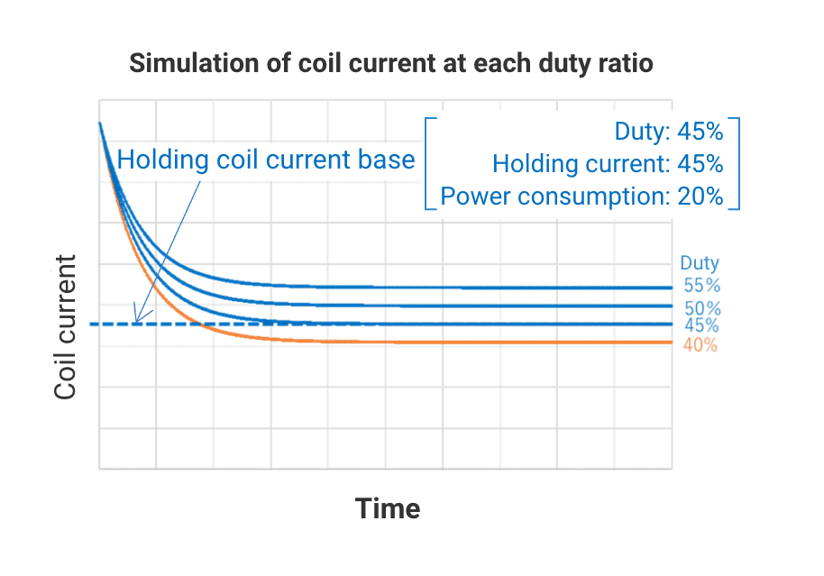
On the other hand, the recommended PWM circuit can meet the criteria for coil current to maintain with a duty ratio of 45% or higher.
Example of G9KA
Typical PWM circuit + Zener diode
* Due to the Zener diode, the PWM circuit may not operate as expected.
Recommended PWM circuit
When using PWM control according to the recommended PWM control circuit, a switch should be mounted in parallel with the Zener diode and bypassed during PWM control. To turn off the relay, first turn off the switch to cut off the applied voltage, then the relay will be normally turned off by the Zener diode + diode.
Recommended PWM control circuit example, peripheral component selection method and example of coil voltage and current waveforms in PWM control circuits
Recommended PWM control circuit example

Example of coil voltage and current waveforms in PWM control circuits

(1) After turning on SW and turning on MOS-FET (M1), apply the rated coil voltage to the control circuit for 0.1~3 seconds.
(2) Turn the MOS-FET (M1) on and off (10kHz or higher is recommended) and switch to PWM control.
(3) When turning off the relay, turn off the SW and then turn off the applied voltage.
* Due to the Zener diode, the PWM circuit may not operate as expected.
Peripheral component selection method
| Symbol | Component | Selection method | Reference Parts *G9KA 12VDC assumed to hold 50% voltage |
|---|---|---|---|
| D1 | Surge absorbing diode |
"If" is equal to or more than the rated coil current. "Vr" is 2 to 3 times the coil voltage. |
Reverse voltage Vr=36V, Forward current If=500mA |
| D2 | Zener diode | Zener voltage specified in catalog. Wattage is the shear head surge reverse current (power), greater than or equal to the relay's rated current (power). |
Zener Vz=36V, Pd=1W (Non-repetitive surge: 3~5W acceptable) |
| M1 | PWM control MOS FET | Select at "Vds" more than the coil voltage plus ZD voltage Vf of D1. Select "Ids" more than the coil current. |
N-Channel, Drain-Source Voltage Vds = 60 V, Drain current Id= 500 mA |
| SW | Mechanical relay for ZD bypass | A small relay, such as a signal relay, is sufficient. | OMRON G5V,G6K,G6S etc. |

When turning off the switching device, in an AC circuit in which the direction of current flow changes, the arc disappears each time the voltage becomes OV. It is relatively easy to interrupt without the need for additional technical ingenuity.
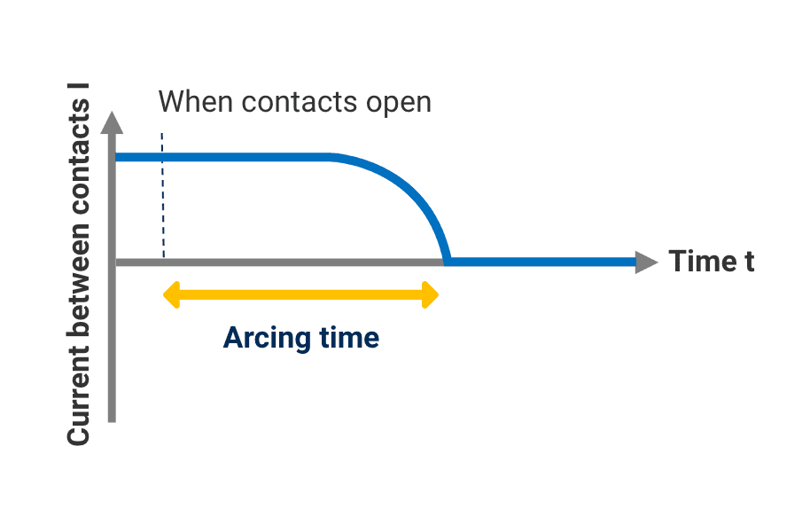
In a DC circuit, however, as the direction of current flow is constant and the arc is continuous, the arc must be forcibly interrupted. Consequently, with high-capacity relays for DC circuits, the larger the voltage or current, the more difficult it is to interrupt the arc.
AC arc
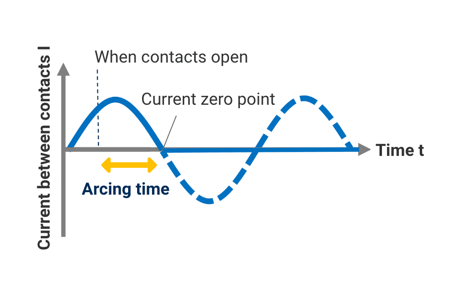
Arc continues from the point where the contacts separate until the next point where the current goes to zero (zero crossing)
DC arc
There are three main ways to interrupt a DC arc.
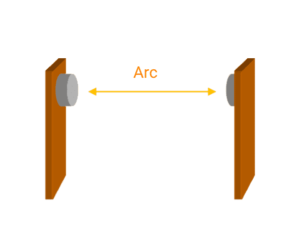
 Method of extending and interrupting
the arc by a larger contact gap
 Method of extending and interrupting
the arc with a magnet
 Method of cooling and interrupting
the arc with enclosed gas
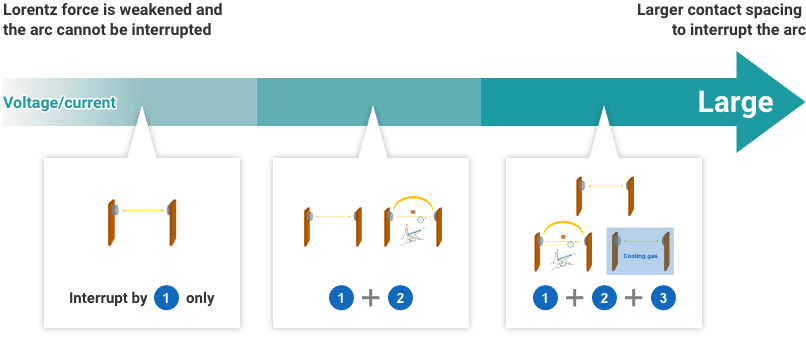
The larger the voltage and current, the greater the arc (discharge) energy and the more difficult it is to interrupt.
Therefore, a combination of arc interrupting methods is used depending on the magnitude of voltage and current.
 Method of interrupting the arc using the contact gap
(1) Interruption by contact gap
The simplest way to interrupt an arc is to interrupt it by the contact gap. This method is generally applied in conjunction with other interrupting techniques due to the larger relay size. Some load conditions, however, create areas where the arc is interrupted by the contact gap alone.
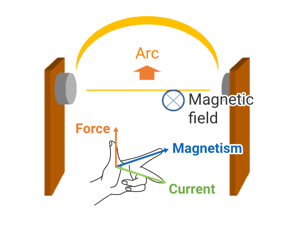
 Method of extending and interrupting the arc with a magnet
The method mainly used in OMRON's PCB power relays is to use magnets to extend and interrupt the arc. Fleming's left-hand rule is applied as a means of extending the arc. The power relays are designed to maximize the arc distance in a limited space by adjusting the distance and angle at which the arc is pulled by the position and type of magnet.
Fleming's left-hand rule
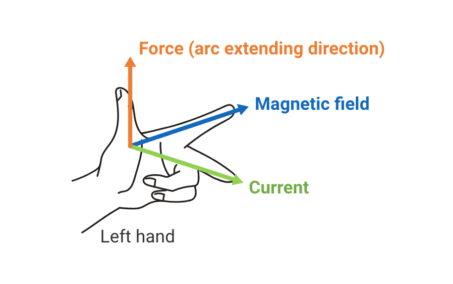
Principle of arc interruption
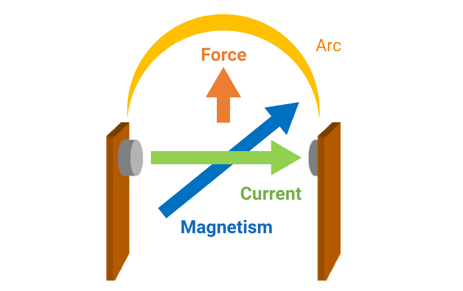
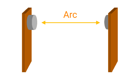
The arc generated between the contacts is pulled in the direction of the force, which causes the arc to curve and gain the distance necessary for interruption.
The length of the arc that can be extended depends on the Lorentz force, which is determined by the current value and the magnetic field. If the current is low, it is difficult to extend the arc.
Therefore, when the current is low, the arc length cannot be extended long enough for the required interruption, and in some cases, the arc cannot be interrupted.
Current is large
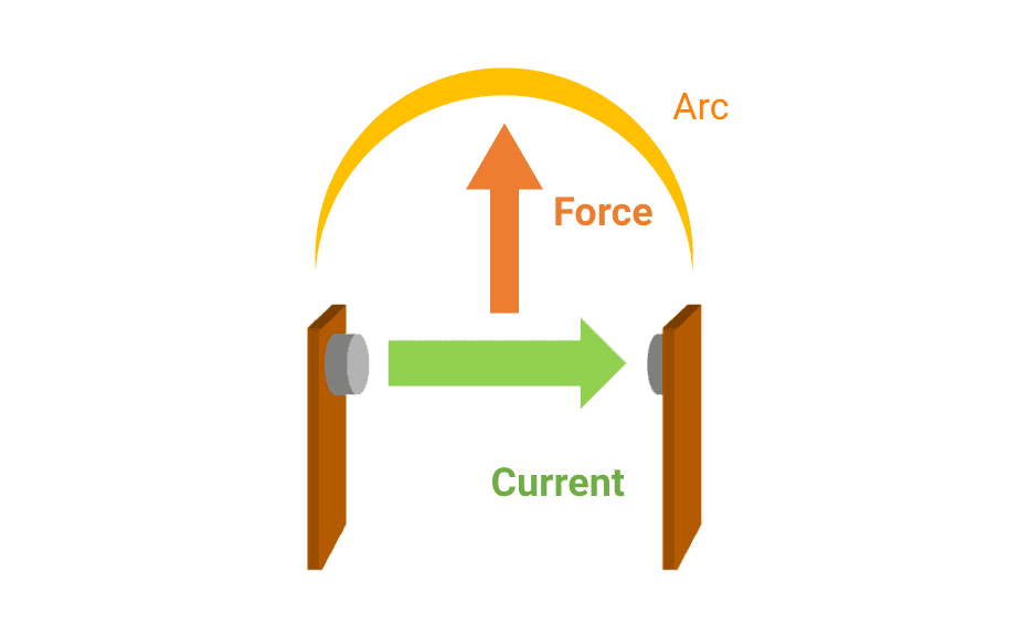
Sufficient force is generated to extend the arc and interrupt.
Current is small
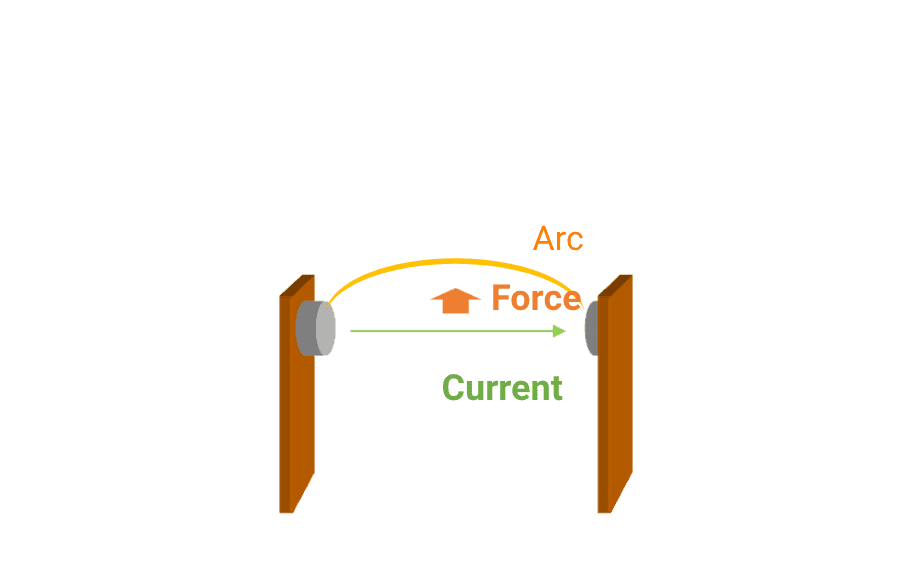
The arc cannot be sufficiently extended to interrupt.
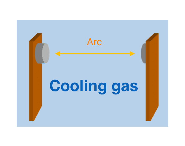
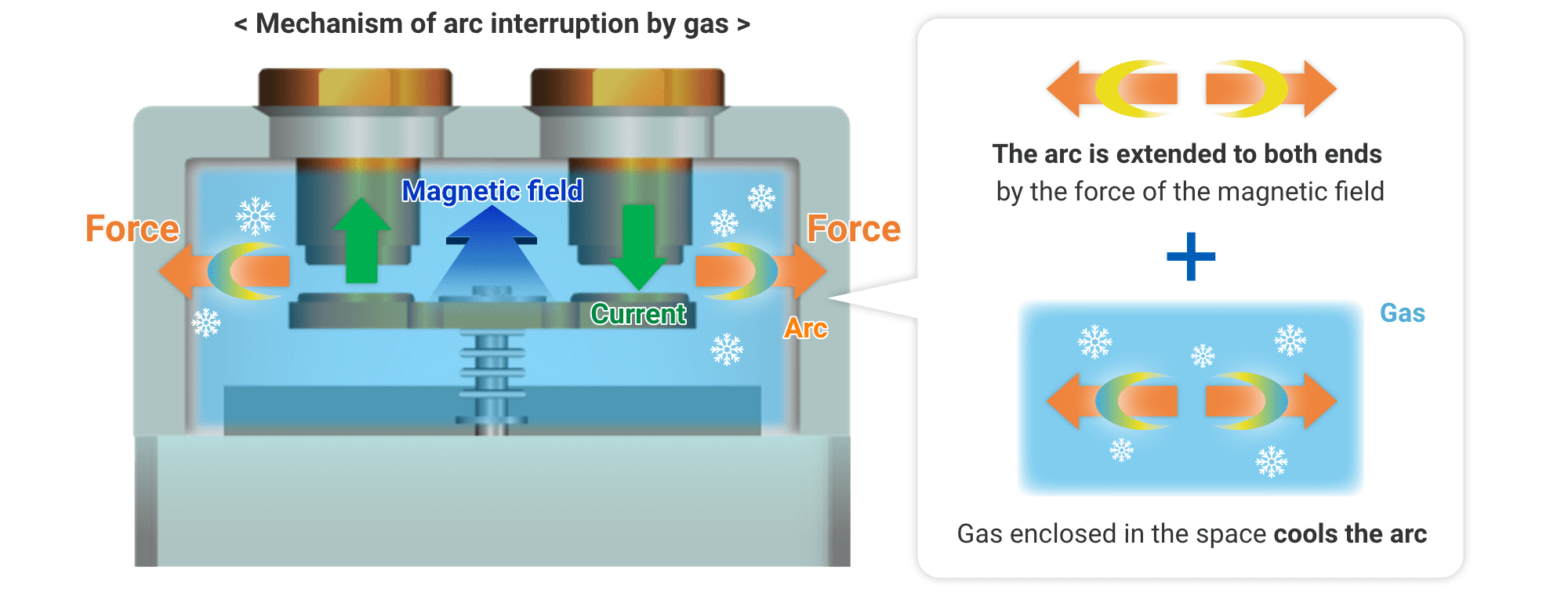
 Method of cooling and interrupting the arc with enclosed gas
OMRON's DC power relays mainly use an enclosed gas to cool and interrupt the arc. In gas-sealed relays, a pressurized gas with high thermal conductivity is sealed in the contact area.
Normally, an arc is generated between the contacts when a DC high voltage is interrupted, and the arc is extended to both ends of the contacts by the force of the magnetic field according to Fleming's left-hand rule. The gas enclosed in the space impedes this arc flow, and the high thermal conductivity of the gas efficiently dissipates arc energy to the outside. The resulting arc extension causes a sudden increase in arc voltage, and the gas effect quickly interrupts the arc inside the air-tight enclosure.

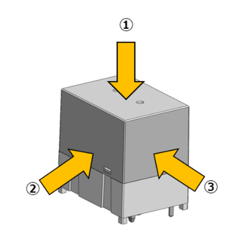
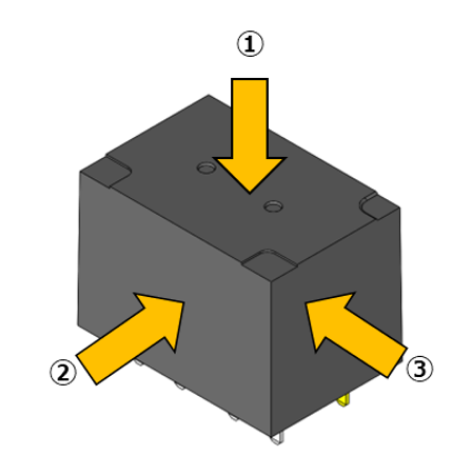
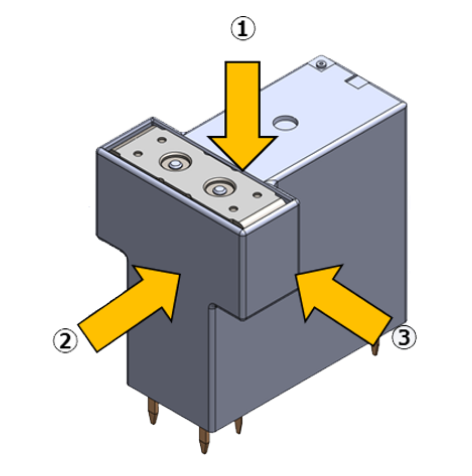
In general, DC power relays incorporate permanent magnets to extend the arc when interrupted. The magnetic field generated by the magnets can affect the operation of surrounding electronic components, especially current sensors (CT: current transformer).
In the case of CT, the magnetic field of the permanent magnet can cause a bias that interferes with accurate current measurements.
This section introduces the magnetic field distribution of OMRON's DC power relays. We hope you will find this information useful for your PCB layout design.
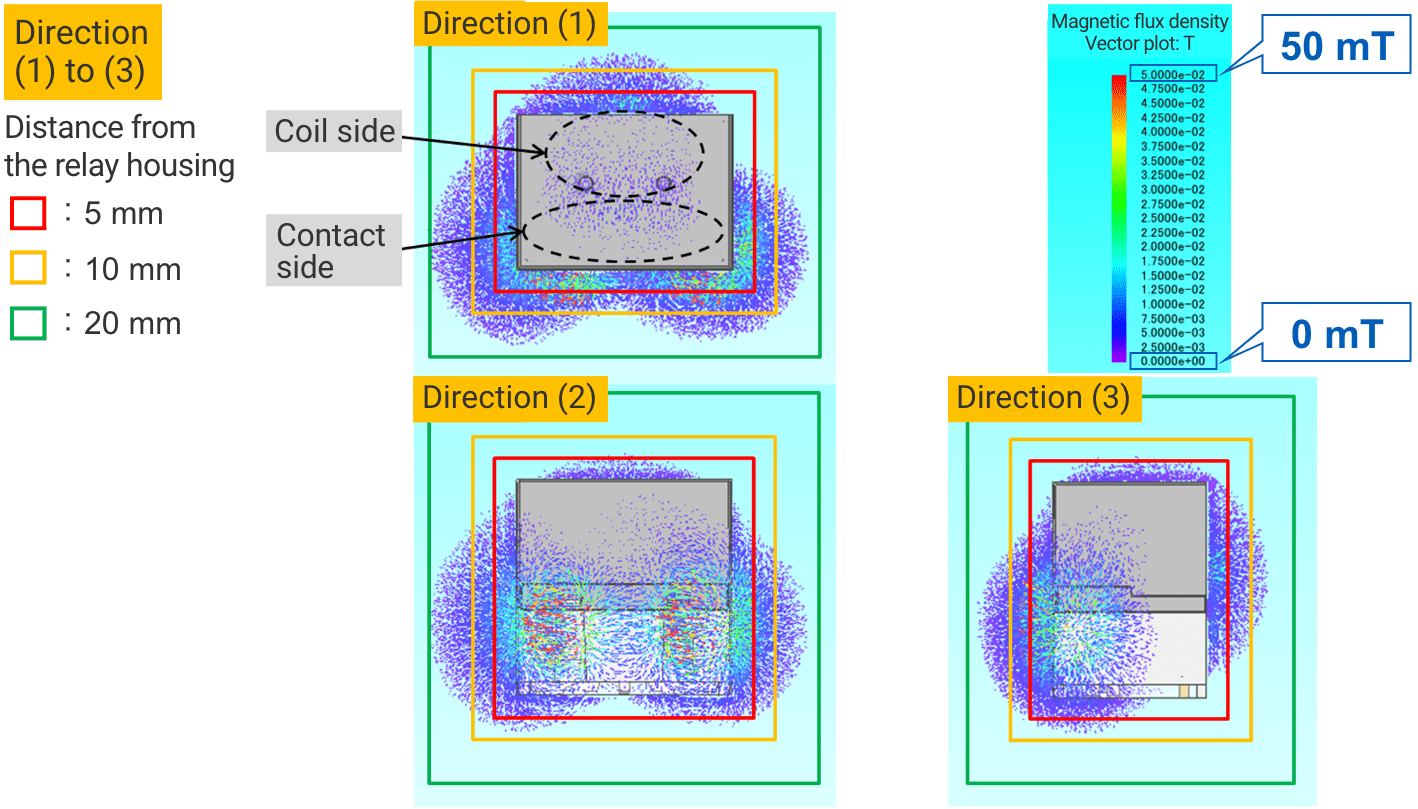
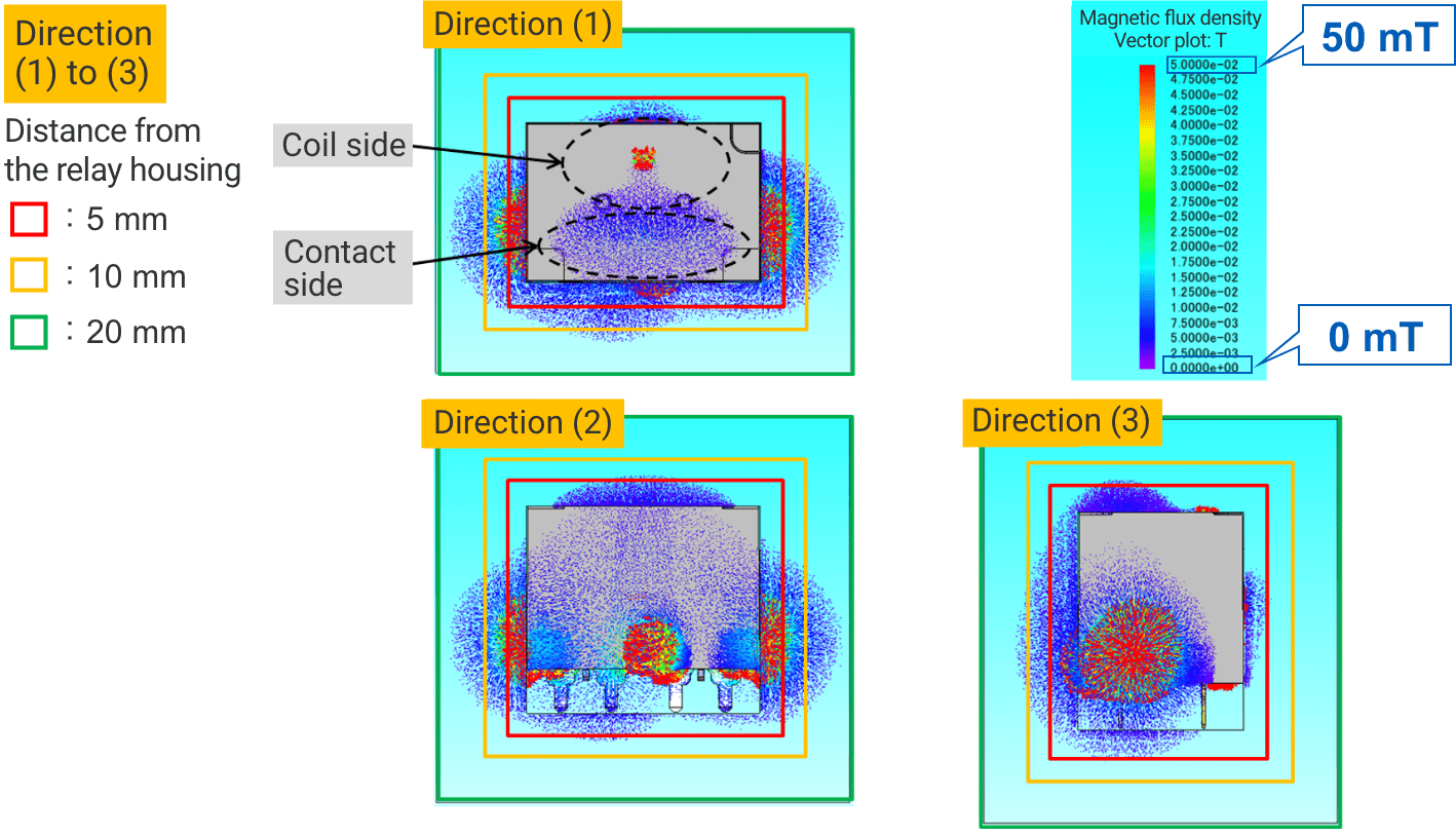
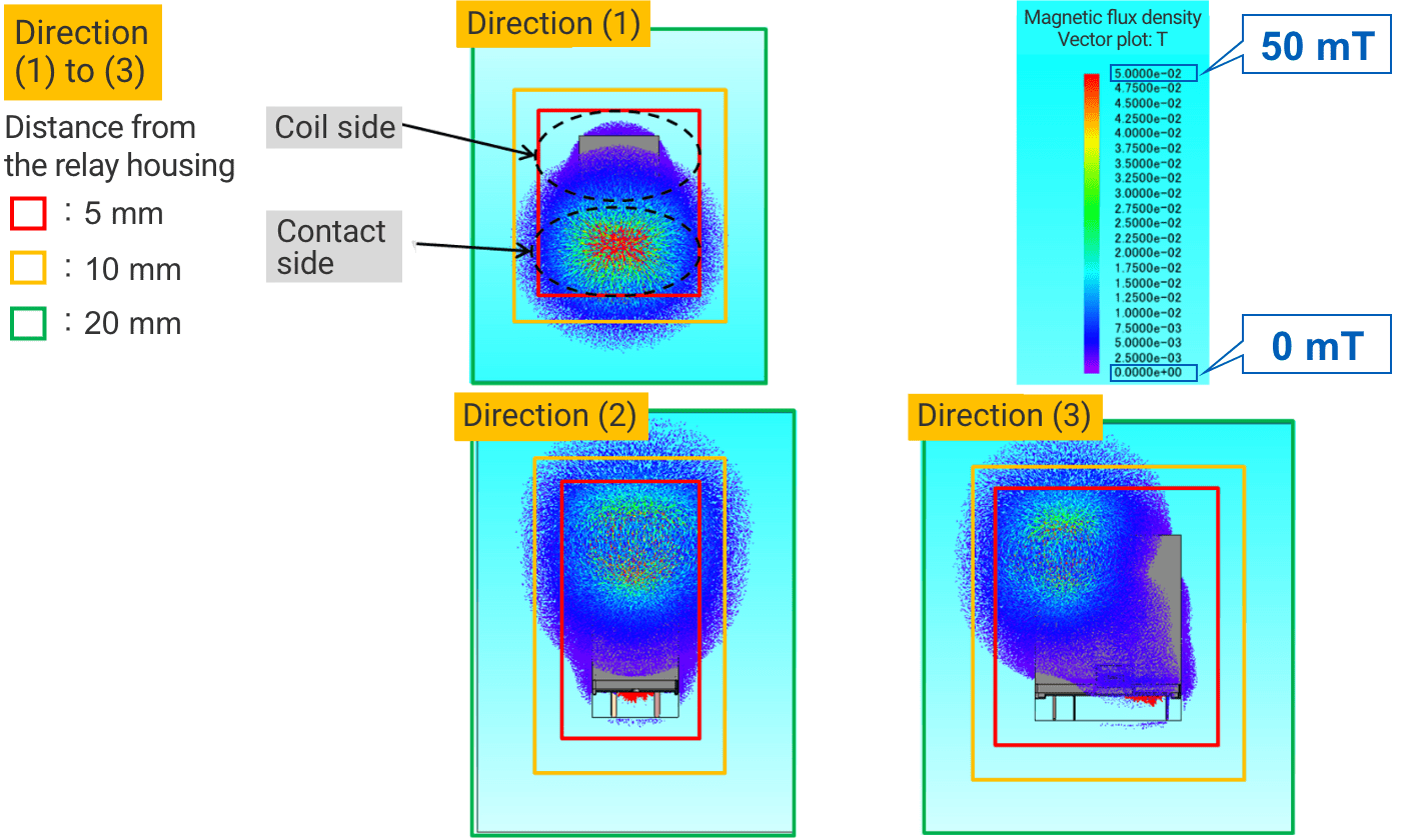
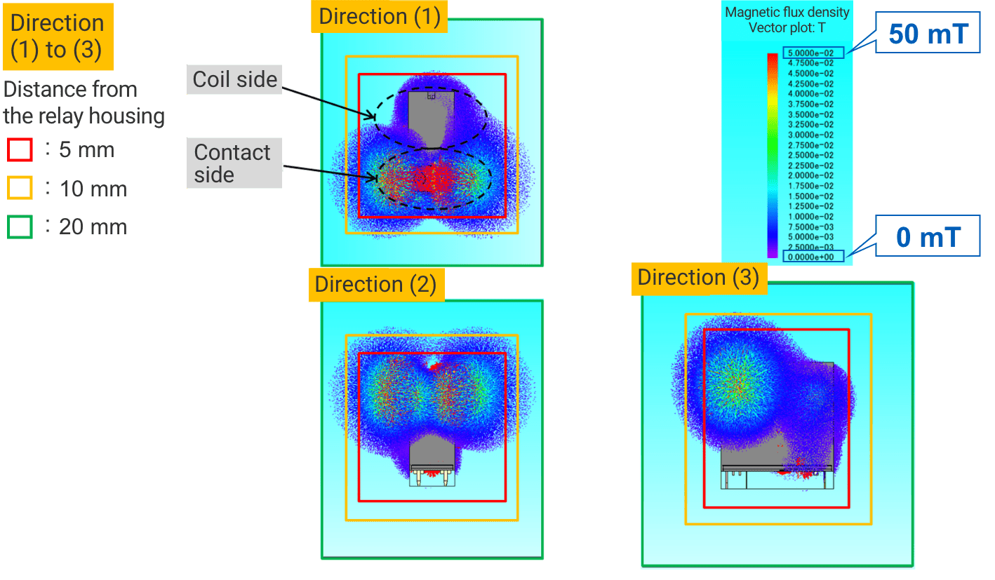
Simulation-based magnetic field analysis predicts that a magnetic flux density can be reduced to several mT by moving the sensor approximately 20 mm away from the surface of the relay housing.
 G9KB-1A
Analysis condition:
Coil applied: 100% applied
Analysis software: J-MAG
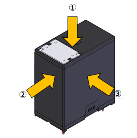
G7L-2A-X
Analysis condition:
Coil applied: 100% applied
Analysis software: J-MAG
G5PZ-1A-X
Analysis condition:
Coil applied: 100% applied
Analysis software: J-MAG
G2RG-2A-X
Analysis condition:
Coil applied: 100% applied
Analysis software: J-MAG

Depending on the capacity range of the DC power relay, there are different things to pay attention to when using it.
Let's take a closer look at each model.
 For DC PCB power relay G7L-X/G5PZ-X
The G7L-X can interrupt a 1,000 VDC / 1 A load. When the current value drops to 0.5 A, however, the Lorentz force makes it difficult to extend the arc, and the load cannot be interrupted. When the current value falls further, however, it enters the area where the load can be interrupted by the contact gap.
G5PZ-X and G7L-X have such areas where interruption becomes unstable.
If the arc cannot be interrupted, there is a possibility of damage to the relay, PCB, and surrounding elements due to abnormal heat generation at the contact.
The figure below is a conceptual diagram showing the area of interruption instability.
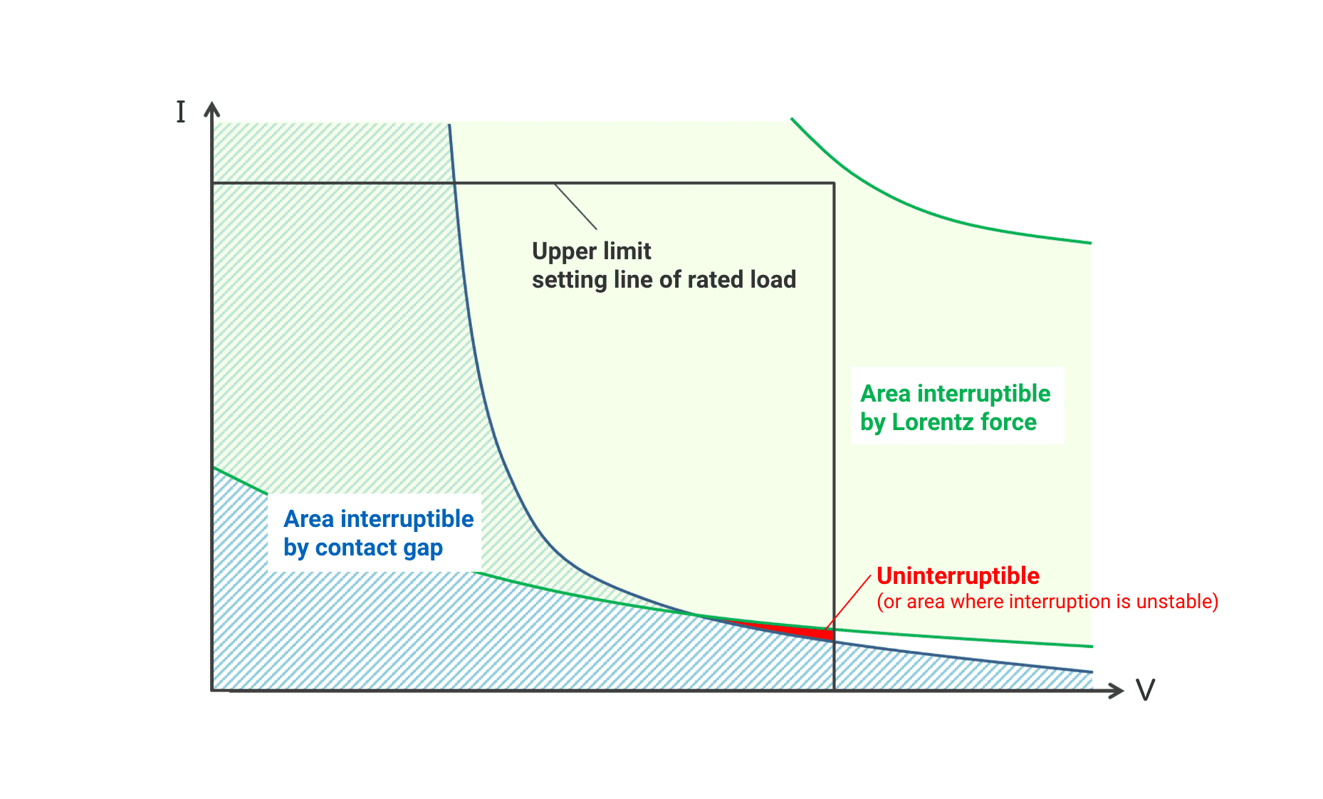
As this area may change depending on the ambient environment, please be sure to check it with the actual device.
 For DC PCB power relay G2RG-X/G9KB
G2RG-X and G9KB also use magnets to control the arc, as with G7L-X and G5PZ-X. As these relays have sufficient contact spacing for the maximum breakdown voltage, no uninterruptible region occurs.


In principle OMRON does not recommend the use of relays electrically connected in series or parallel (except G5PZ-X).
Here are some concerns with such usage.
 Partial voltage when relays are connected in series
When used with a DC load, connecting relays in series divides the voltage in two and it may be possible to interrupt a larger voltage than with a single relay. For example, if two relays with a rated switching voltage of 200 VDC / 20 A are connected in series, it may be possible to interrupt 400 VDC / 20 A. For G5PZ-X, this type of use can be recommended.(See individual datasheet for details)
G5PZ-X connection example
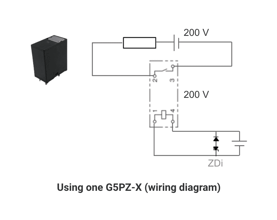
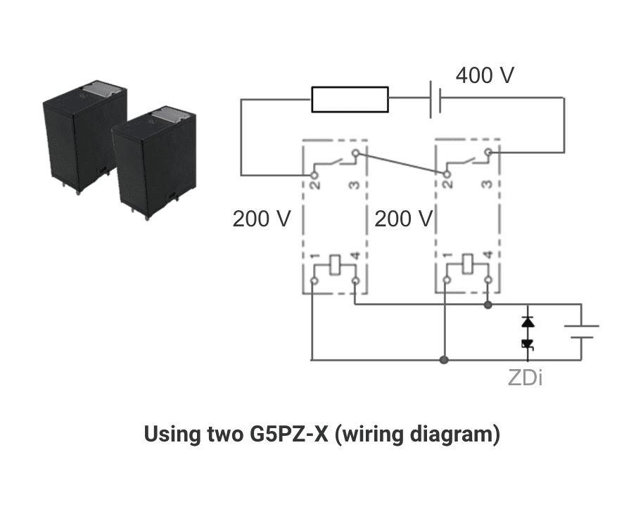
Each relay can interrupt 200 VDC each, up to 400 VDC in total.
 Cautions for series connection
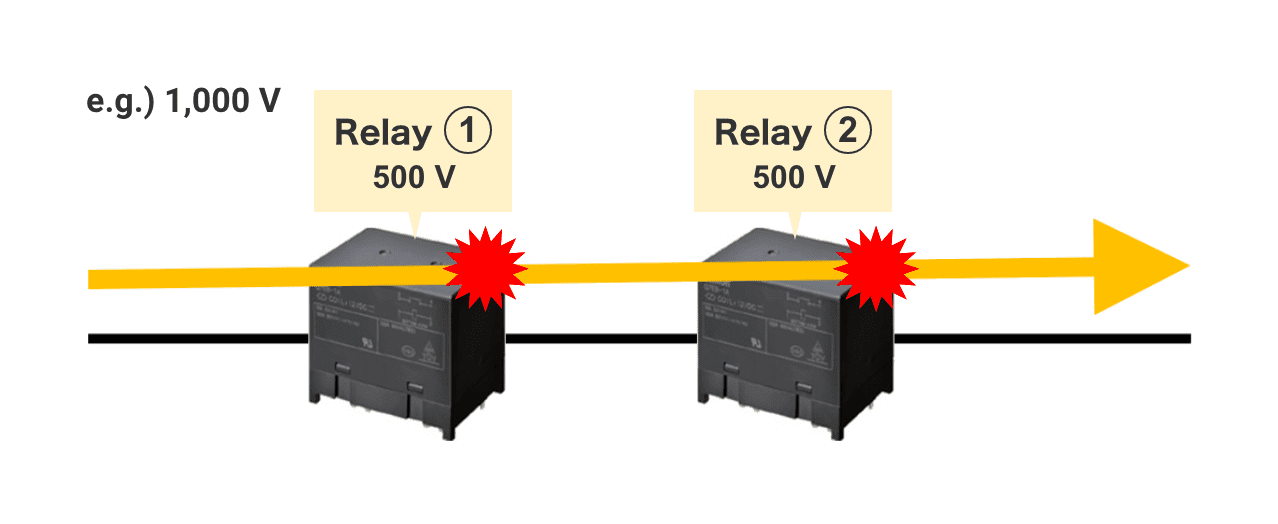
If the reset times of relays in series connection vary, or if one relay is damaged (welded), arcs may momentarily concentrate on one relay, leading to its failure or damage.
In the ideal state, relays (1) and (2) operate simultaneously and 1/2 the system voltage is applied to (1) and (2)
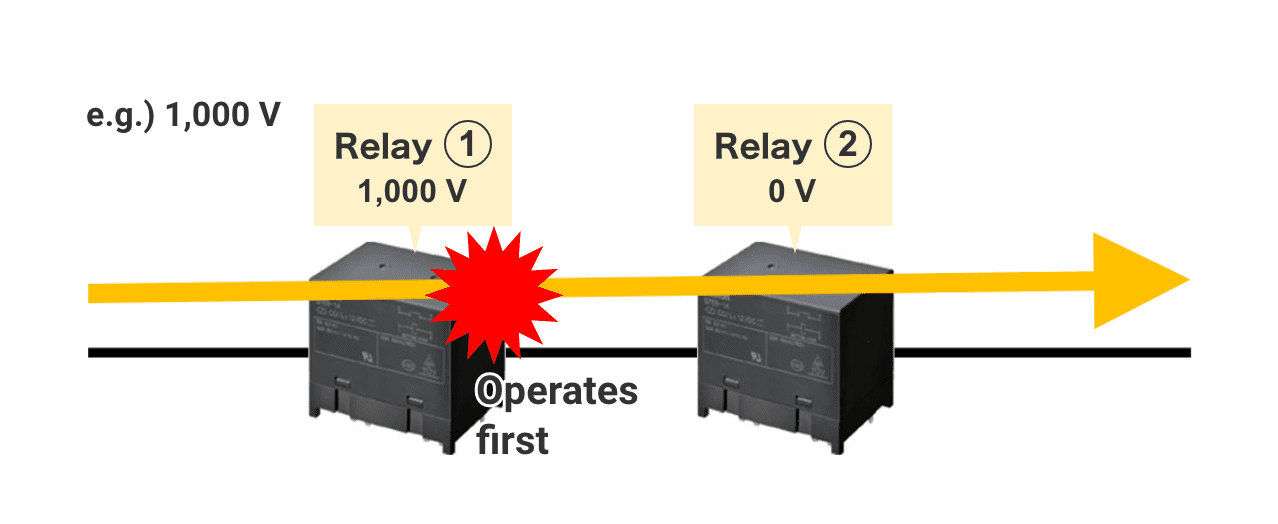
If relay (1) operates before relay (2), an arc occurs with full voltage applied to (1)
V(1) > V(2)
 Shunt current when relays are connected in parallel
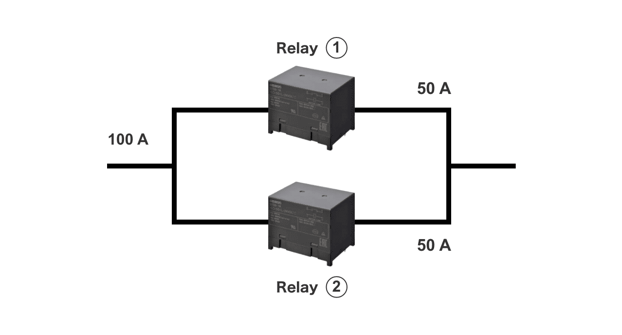
A larger current may be energized by connecting relays in parallel. For example, two relays that can energize 200 A may be connected in parallel to energize 400 A.
However, OMRON does not recommend parallel use.
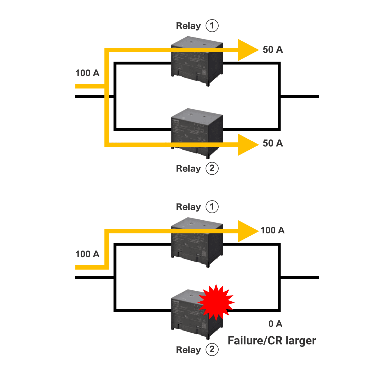
In the ideal state, relays (1) and (2) operate simultaneously and the currents flowing through (1) and (2) are the same.
 Cautions for parallel connection
If one relay fails and cannot be energized, more current will flow to the other relay, resulting in its failure. In addition, since the contact resistance of each relay is not exactly the same, current concentrates in the relay with the lowest contact resistance, leading to its failure as well.
To prevent this, it is necessary to use a relay with a rating that has a margin in excess of the circuit current, or install a current sensor or fuse in the current line of each relay to prevent overcurrent.
Also, when a load is interrupted, the interrupting arc is always concentrated in one of the relays, resulting in a high risk of failure. Thus, control is necessary to ensure that no load (0 A) is applied at the time of interruption, or that the current is kept within the rated current of one relay.
Note that OMRON does not guarantee nor recommend the operation of this countermeasure example.
In the ideal state, relays (1) and (2) operate simultaneously and the currents flowing through (1) and (2) are the same.
There is, however, a risk of current being concentrated in one relay due to a failure of one of the relays or due to differences in contact resistance.
 Countermeasure examples
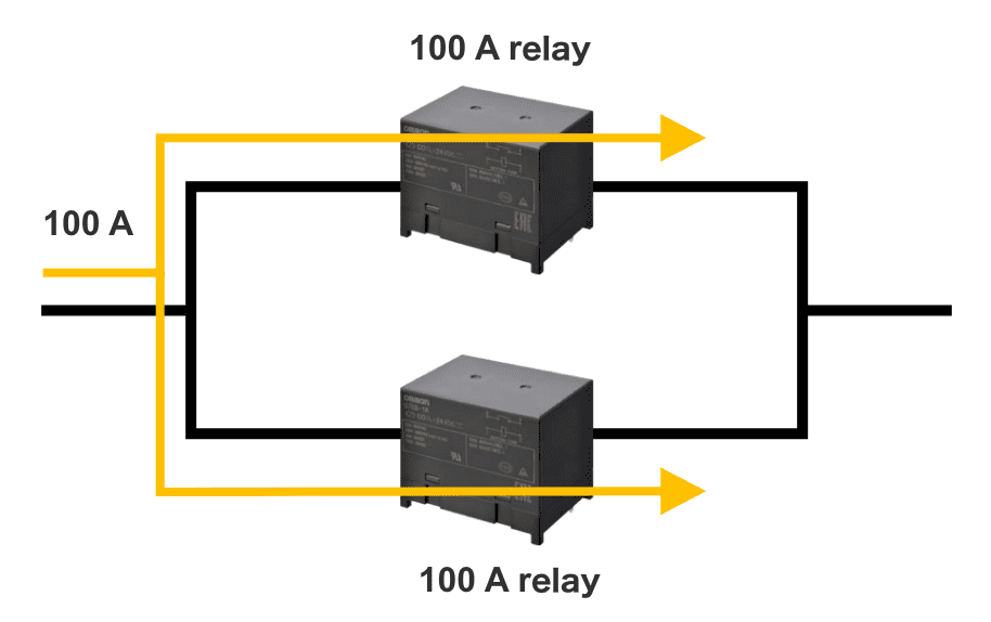
1) Select a relay with ample current capacity
2) Insert resistor for current balance
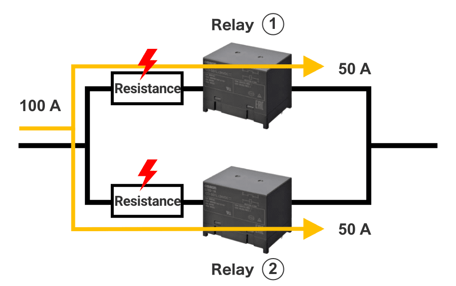
Loss (heat generation) due to resistance is an issue

This section describes the behavior of a relay when a large current, such as a short-circuit current, flows through the relay.
Depending on the magnitude of the current, three major phenomena occur.

| Current value | Small | Medium | Large |
|---|---|---|---|
| Phenomenon | Electromagnetic repulsion is small and the contacts do not open.(Time setting is necessary because contacts may melt) | Electromagnetic repulsion causes the contacts to open, but welding occurs. | Electromagnetic repulsion causes the contacts to open, and the arc continues.(Continued use is possible in case of fuse coordination) |
| Relay status | Continuous use is possible if the contact area is energized for a period of time during which melting and welding does not occur. | Electromagnetic repulsion causes the contacts to open, and welding occurs when the contacts re-contact with the arc generated. Continued use is not possible. |
Contacts open by electromagnetic repulsion, but the repulsion force is so large that it is difficult for the contacts to re-contact. In the case of fuse coordination, the contact that interrupts the current by the fuse before it is re-contacted is worn, but can continue to be used. (However, if the arc continues for a long time, it will explode and become unusable) |
< Electromagnetic repulsion due to Lorentz force >
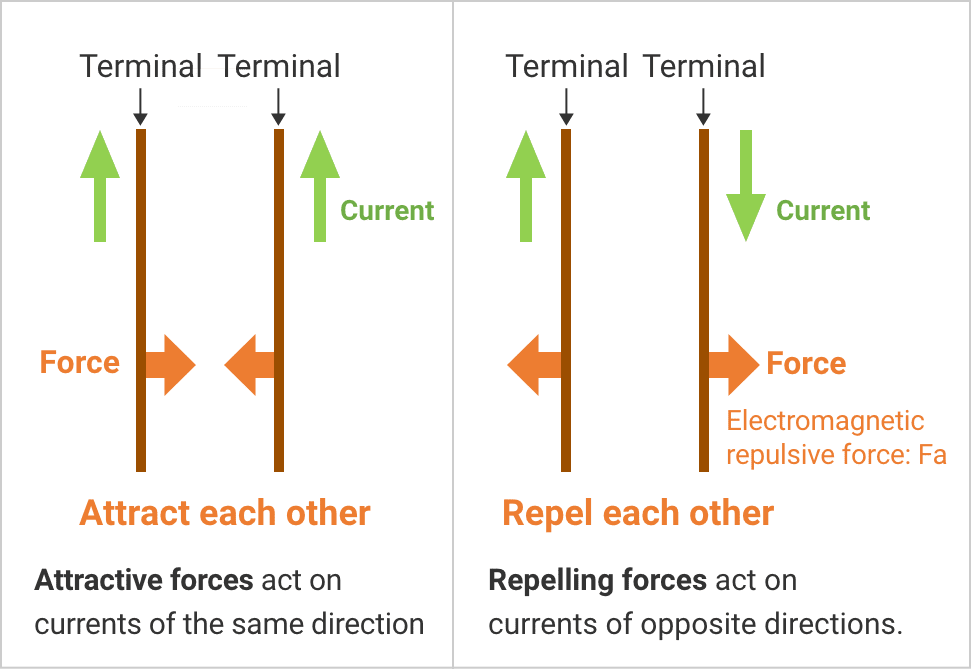
When a current flows through a relay, the Lorentz force, which is proportional to the magnitude of the current, causes a repulsive force (electromagnetic repulsive force Fa) between the contacts. Since the contacts come to contact at a point, current flows through the contact surface as shown in the figure below.
<Electromagnetic repulsive force generated on the contact surface>

The contacts come to contact at a point, the current flows in the opposite direction between the contacts, and an electromagnetic repulsive force acts.
 For Electromagnetic repulsive force (Fa) < Contact pressure (Fb)
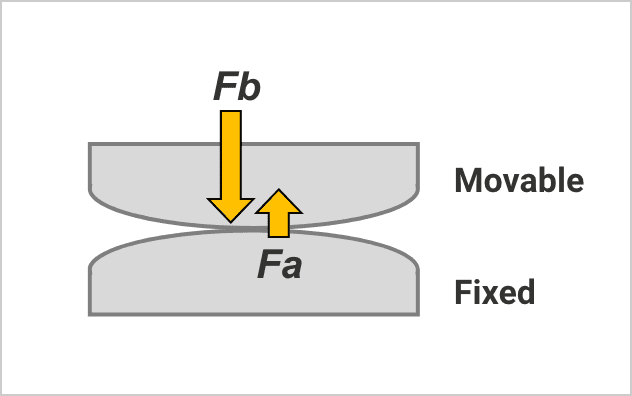
The spring force exerts a force (contact pressure Fb) on the relay contacts that pushes them against each other. If the contact pressure (Fb) is sufficiently large, the electromagnetic repulsive force (Fa) has no effect and contact welding does not occur. Contact can be opened without a problem.
 For Electromagnetic repulsive force (Fa) ≤ Contact pressure (Fb)
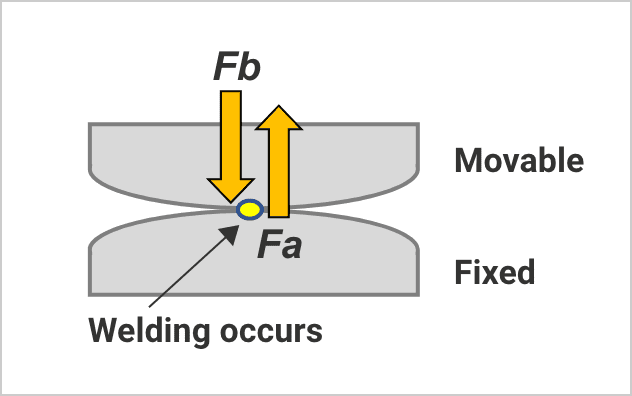
In the region where the electromagnetic repulsive force (Fa) does not exceed the force (Fb) pressing the contacts to each other, the contacts do not open. But the force pressing the contact points against each other is reduced due to the generation of Fa. This increases the contact resistance of the contact area, which in turn increases the Joule heat generated there, melting the contacts and possibly causing welding.
 For Electromagnetic repulsive force (Fa) > Contact pressure (Fb)
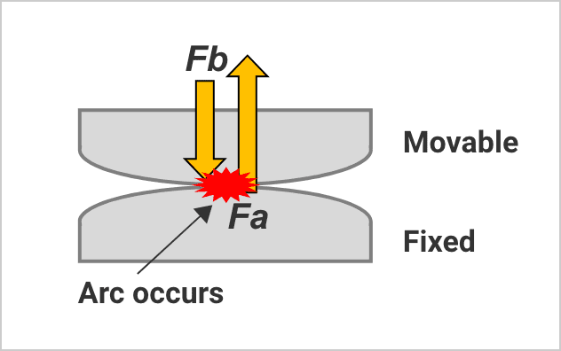
Furthermore, if the current increases further and the electromagnetic repulsive force (Fa) exceeds the contact pressure (Fb), the contacts open. In the process, an arc is generated between the contacts, and the arc heat can melt the contacts and the area around the contacts, causing burnout (smoke and fire) and, in some cases, an explosion due to rapid heating.
Thus, when a large current is energized, the relay may be destroyed depending on the magnitude and duration of that current.
Please consider adopting the product after evaluation under actual load conditions.

The increase in heat generated by the equipment becomes an issue when the application's capacity and current become higher. Heat generation shortens the life of equipment, requiring cooling mechanisms such as fans and heat sinks. Using a cooling mechanism leads to larger equipment and higher costs. One of the factors that causes equipment to generate heat is the relays mounted on the PCB inside the equipment.
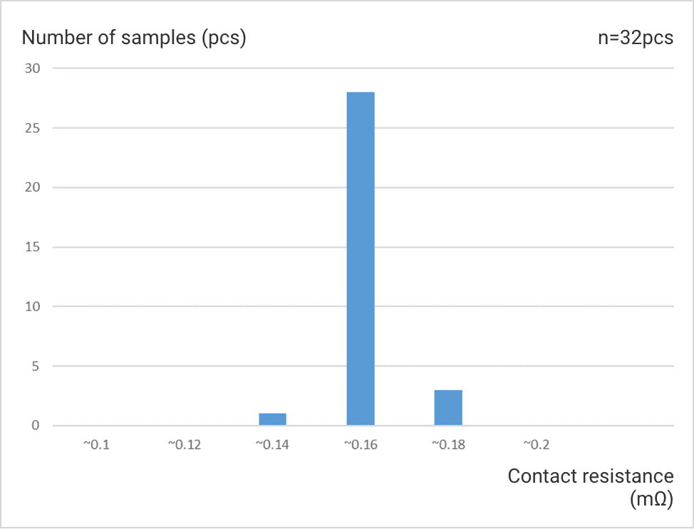
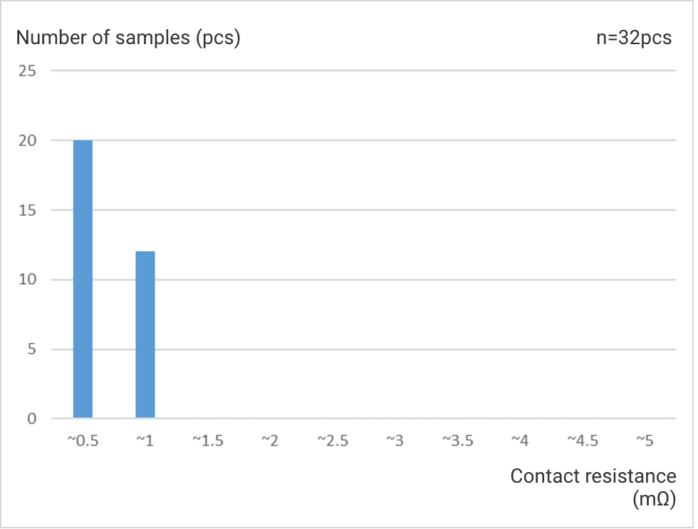
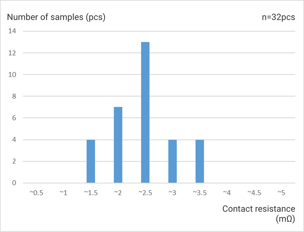
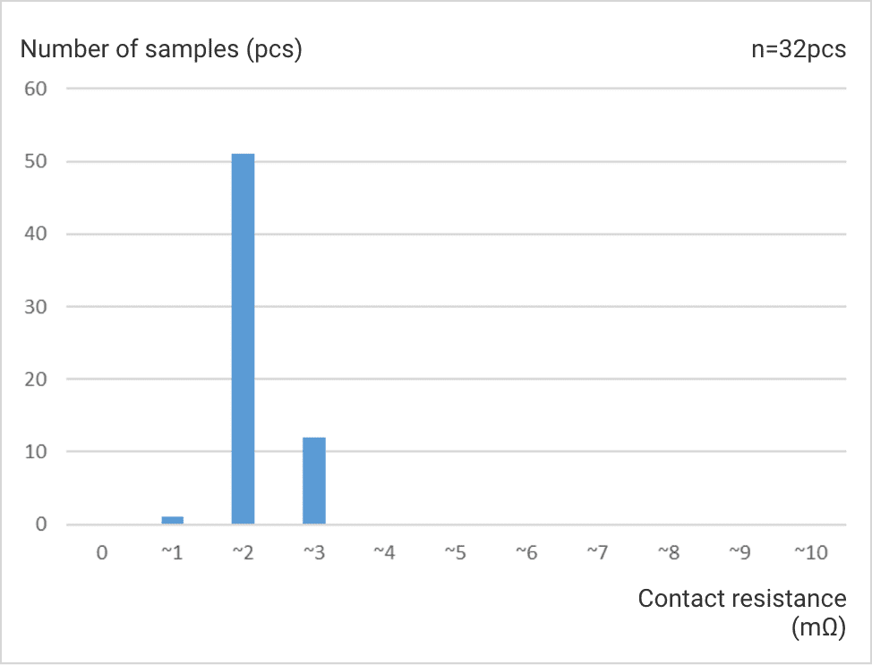
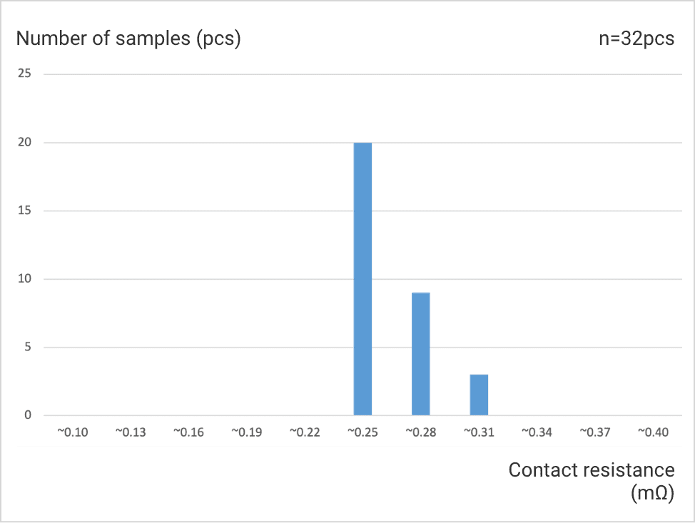
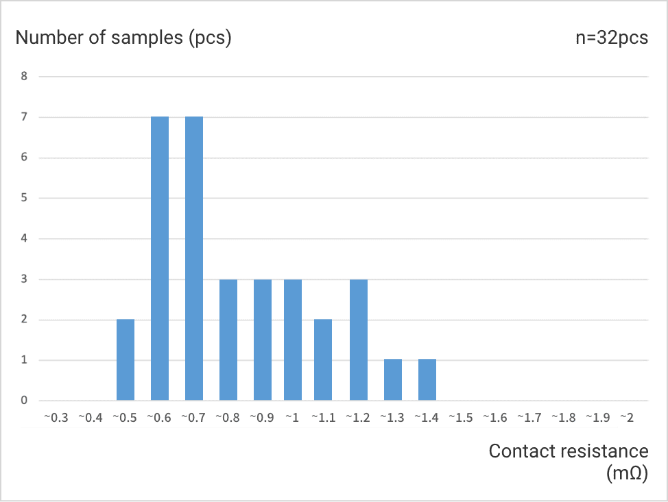
The contact resistance of a typical high-capacity power relay is 100 mΩ. OMRON, however, also offers a lineup of high-capacity power relays with ultra-low contact resistance as low as 0.2 mΩ, contributing to lower heat generation in equipment. The graphs below compare the specification and actual values of contact resistance. Please check them as a reference when designing.
*OMRON guarantees the specification, not the actual performance.
G9KA
Specification : 0.2 mΩ max.
G7EB
Specification : 5 mΩ max.
G9KB
Specification : 5 mΩ max.
G7L-X-SI
Specification : 10 mΩ max.
G9TB
Specification : 0.4 mΩ max.
G9TA
Specification : 2 mΩ max.

The need to “realize a larger load energization with PCBs” has rapidly been increasing, and OMRON is offering PCB relays of the several hundred A class. However, many customers may be actually wondering “What kind of PCB design and solder implementing condition should be adopted to control a large current over 30A with a PCB relay?”
Let’s talk about some ideas on PCBs and solders when energizing a large current.
 Concept of large-current PCBs when high-capacity power relays are used
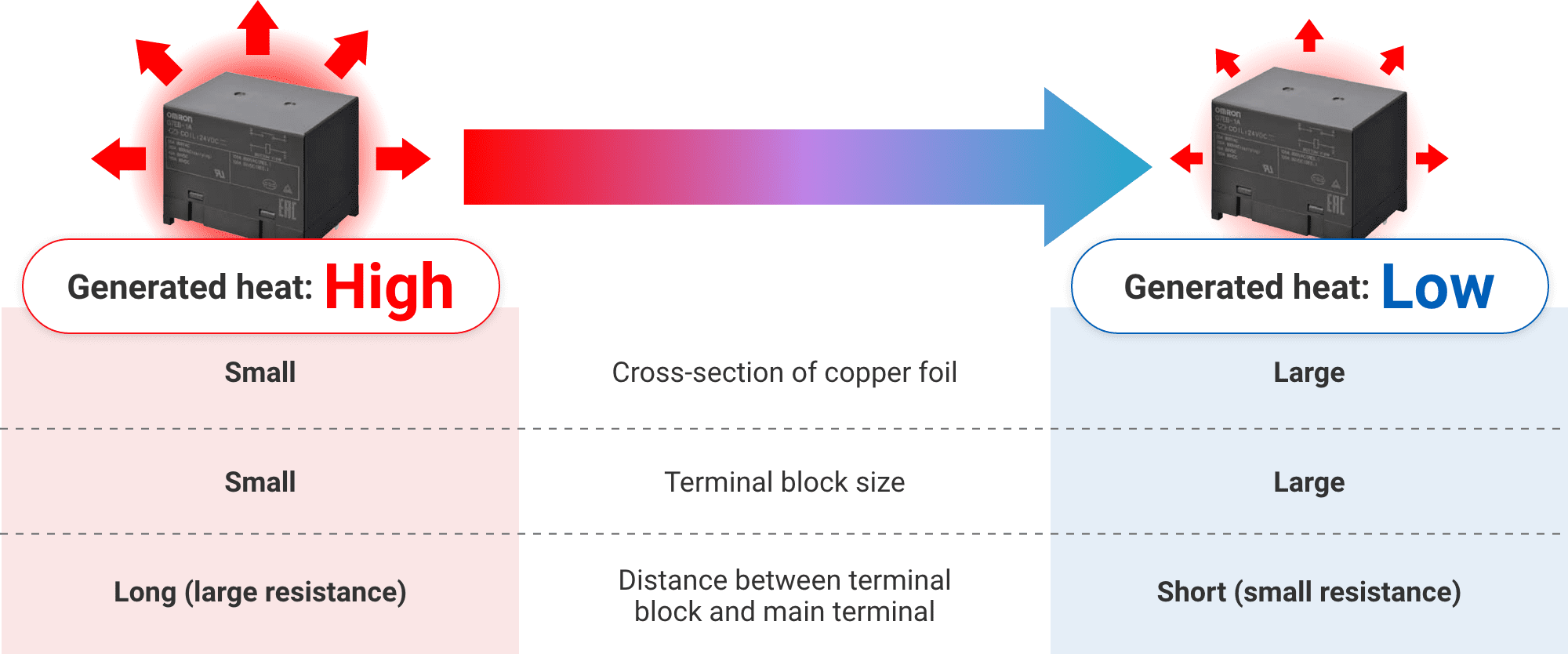
When controlling a large current on PCBs, suppressing the heat is key for successful process. Therefore, the designs of circuit PCBs around the relay are important.
Copper foil is used in circuit boards as a conductor to transfer electrical signals and currents between various parts and circuits. As the current increases, the heat generation at various parts including relays and copper foil sections on PCBs also increases. This induces a rise in the PCB's temperature and reduces its durability. Therefore, lowering the resistance of the energized part is necessary depending on the amount of the current. The PCBs with higher durability for larger currents can be made by enlarging the cross-section (thickness x width) of the copper foil.
Recommended PCB cross-sections vary for rated currents of different relays. A copper foil on PCBs has a specific thickness; therefore, the cross-section of the copper foil is designed in balance with the copper foil width. In general, other matters such as the size of the terminal block and the distance to the main terminal also affect the temperature increase of PCBs in addition to the cross-section.
The following is the result of designing the PCB so that the PCB temperature is 120°C or lower when the rated current is energized, the relay coil voltage is set as the holding voltage, and the natural convection current of 1.5 m/s is given.
G9KC-4A1B
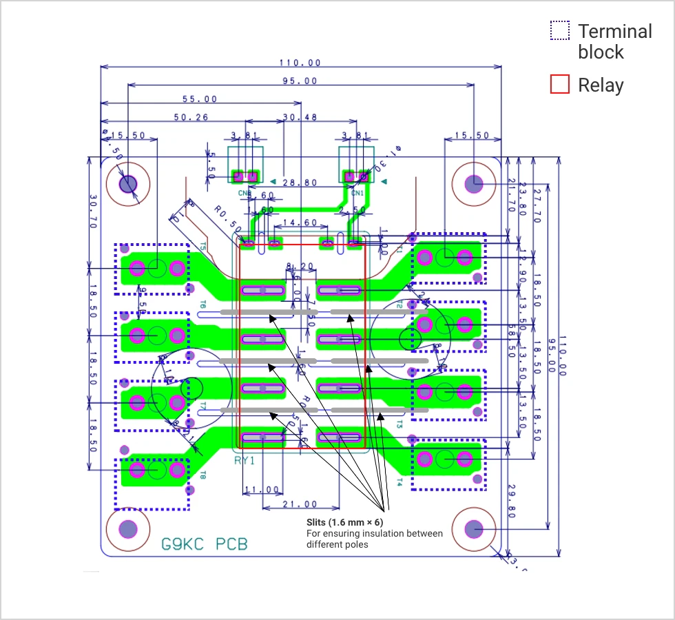
| (1) | |
| Copper foil cross-section area | 3.6 mm2 (W6 mm x T0.3 mm x 2 sheets) |
|---|---|
| PCB thickness | Approx. 2.1 mm |
| PCB design conditions | Ambient temperature 85℃, rated current (40 A)、holding voltage, natural convection 1.5 m/s, PCB temperature 120℃ or lower |
| Terminal block size | M4 |
| Cable wire diameter | 8 sq |
| Clearance between terminal block and relay main terminal |
13 mm |

| (2) | |
| Copper foil cross-section area |
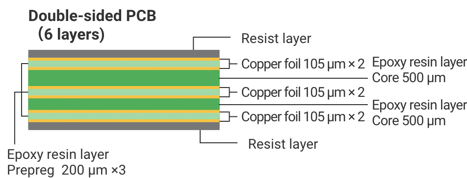
3.78 mm2 (W6 mm x T0.105 mm x 6 sheets) |
|---|---|
| PCB thickness | Approx. 2.4 mm |
| PCB design conditions | Ambient temperature 85℃, rated current (40 A)、holding voltage, natural convection 1.5 m/s, PCB temperature 120℃ or lower |
| Terminal block size | M4 |
| Cable wire diameter | 8 sq |
| Clearance between terminal block and relay main terminal |
13 mm |
Note: The above conditions are only based on our own evaluations. They do not guarantee that the PCB temperature will stay at 120ºC or lower.
Please determine your PCB conditions only after your own evaluation.
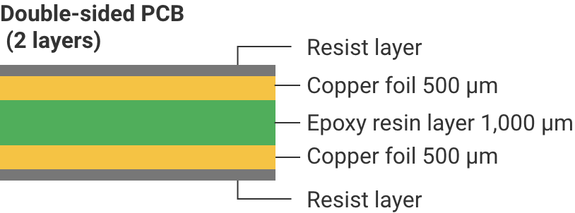
G9KA-1A-E
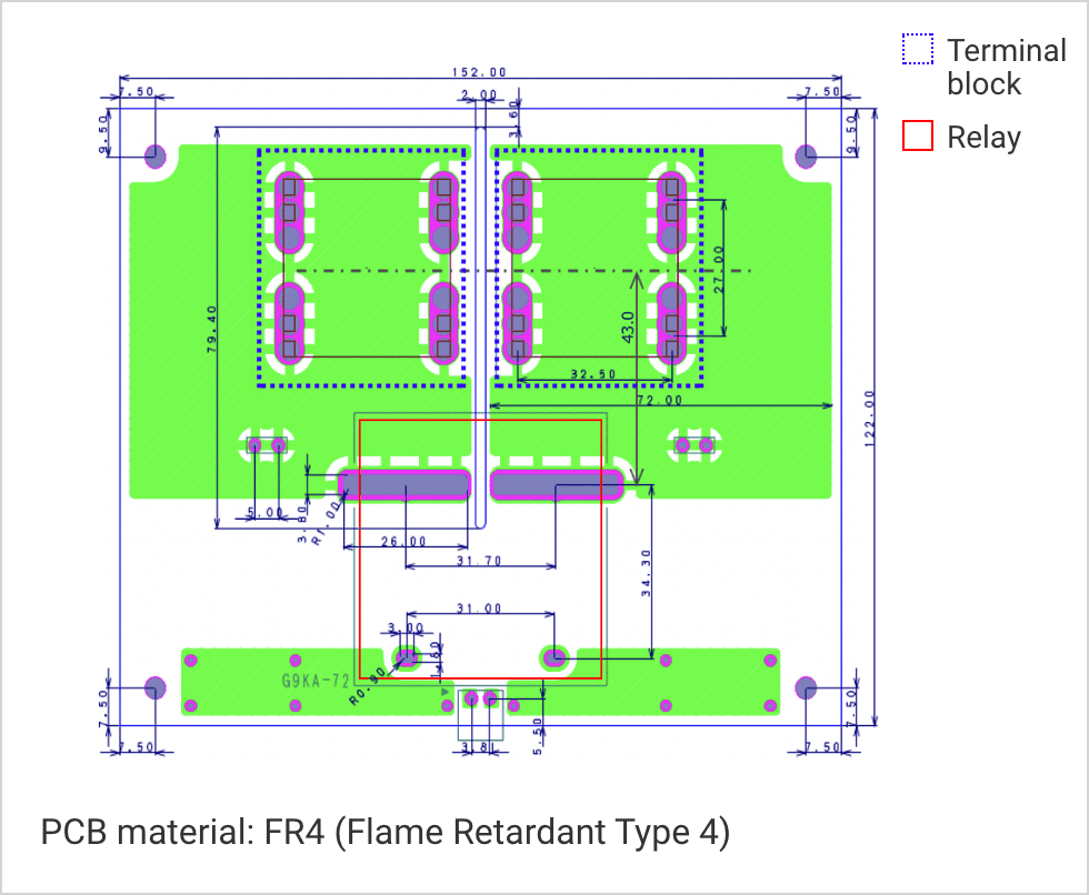
| Copper foil cross-section area | 72 mm2 (W72 mm x T500 μm x 2 sheets) |
|---|---|
| PCB thickness | Approx. 2.1 mm |
| PCB design conditions | Ambient temperature 85ºC, rated current (300 A), holding voltage, natural convection 1.5 m/s, PCB temperature 120ºC or lower |
| Terminal block size | M8 |
| Cable wire diameter | 185 sq |
| Clearance between terminal block and relay main terminal |
43 mm |
Note: The above conditions are only based on our own evaluations. They do not guarantee that the PCB temperature will stay at 120ºC or lower.
Please determine your PCB conditions only after your own evaluation.
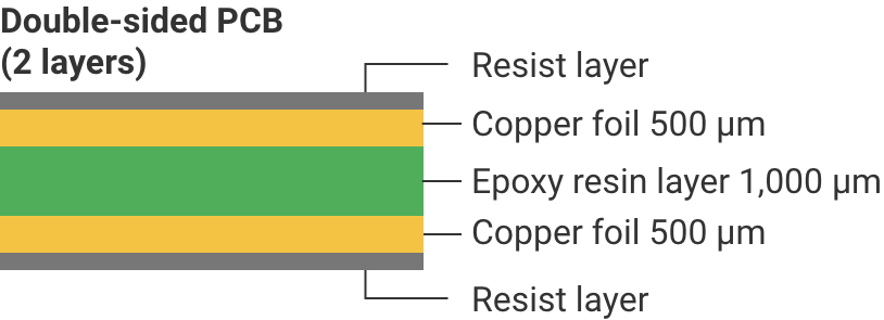
G9KA-1A
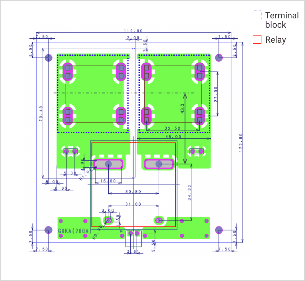
| Copper foil cross-section area | 45 mm2 (W45 mm x T500 μm x 2 sheets) |
|---|---|
| PCB thickness | Approx. 2.1 mm |
| PCB design conditions | Ambient temperature 85ºC, rated current (260 A), holding voltage, natural convection 1.5 m/s, PCB temperature 120ºC or lower |
| Terminal block size | M8 |
| Cable wire diameter | 150 sq |
| Clearance between terminal block and relay main terminal |
43 mm |
Note: The above conditions are only based on our own evaluations. They do not guarantee that the PCB temperature will stay at 120ºC or lower.
Please determine your PCB conditions only after your own evaluation.
G9KB-1A
On a board with G9KB (initial CR product) mounted, the following board configuration is required to keep the board temperature below 120°C (ambient temperature: 85°C, airflow: 1.5 m/s) when 50 A is energized:
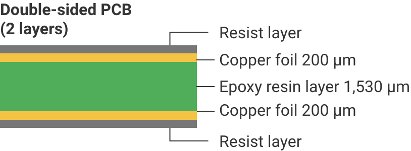
1. For a double-sided board with 200 μm copper foil: total cross-sectional area of 12.5 mm2, pattern width of 31.25 mm
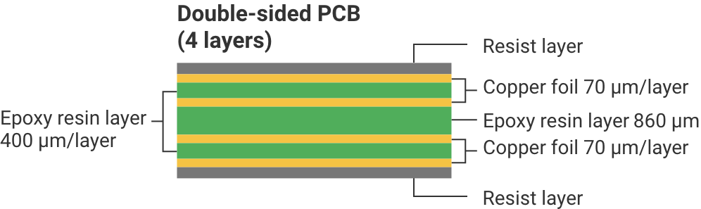
2. For a 4-layer board with 70 μm copper foil: total cross-sectional area of 8.75 mm2, pattern width of 31.25 mm
*Note: The temperature rise is smaller for configuration (1) (double-sided board) compared to configuration (2) (4-layer board).
Please consider the ease of procurement of the board when designing.
Please note that these values are for reference only. When using the board in practice, please conduct your own evaluation and determine the board conditions accordingly.
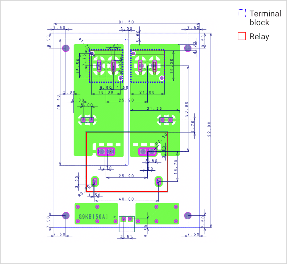
| (1) | |
| Copper foil cross-section area | 12.5 mm2 (W31.25 mm x T200 μm x 2 sheets) |
|---|---|
| PCB thickness | Approx. 2.0 mm |
| PCB design conditions | Ambient temperature 85ºC, rated current (50 A), holding voltage, natural convection 1.5 m/s, PCB temperature 120ºC or lower |
| Terminal block size | M5 |
| Cable wire diameter | 10 sq |
| Clearance between terminal block and relay main terminal |
53.8 mm |
| (2) | |
| Copper foil cross-section area | 8.75 mm2 (W31.25mm x T70 µm x 4 sheets) |
|---|---|
| PCB thickness | Approx. 2.0 mm |
| PCB design conditions | Ambient temperature 85ºC, rated current (50 A), holding voltage, natural convection 1.5 m/s, PCB temperature 120ºC or lower |
| Terminal block size | M5 |
| Cable wire diameter | 10 sq |
| Clearance between terminal block and relay main terminal |
53.8 mm |
Note: The above conditions are only based on our own evaluations. They do not guarantee that the PCB temperature will stay at 120ºC or lower.
Please determine your PCB conditions only after your own evaluation.
G7EB-1A-E
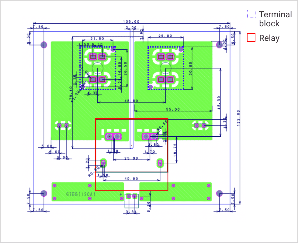
| Copper foil cross-section area | 55 mm2 (W55 mm x T500 μm x 2 sheets) |
|---|---|
| PCB thickness | Approx. 2.1 mm |
| PCB design conditions | Ambient temperature 85ºC, rated current (120 A), holding voltage, natural convection 1.5 m/s, PCB temperature 120ºC or lower |
| Terminal block size | M6 |
| Cable wire diameter | 50 sq |
| Clearance between terminal block and relay main terminal |
48.30 mm |

Note: The above conditions are only based on our own evaluations. They do not guarantee that the PCB temperature will stay at 120ºC or lower.
Please determine your PCB conditions only after your own evaluation.
 Concept of solder flow mounting on large current PCBs
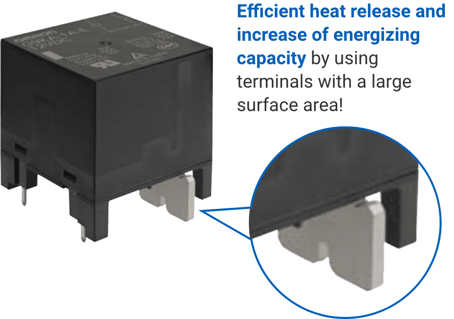
When a large current flows, heat generation always increases. Therefore, to suppress the temperature increase of the terminal and overheating, a terminal with a large surface area is necessary for high-capacity power relays. You may wonder how you can solder-mount a large terminal on a PCB.
When conducting the solder-mounting, the temperatures of the terminal and PCB are important. Large terminals have high heat dissipation. Therefore, the solder around the terminal is cooled down, and raising the solder temperature to an appropriate temperature becomes difficult. In general, the preheating process before solder mounting is one of the important processes. It is the same for the flow soldering process of high-capacity PCB relays.
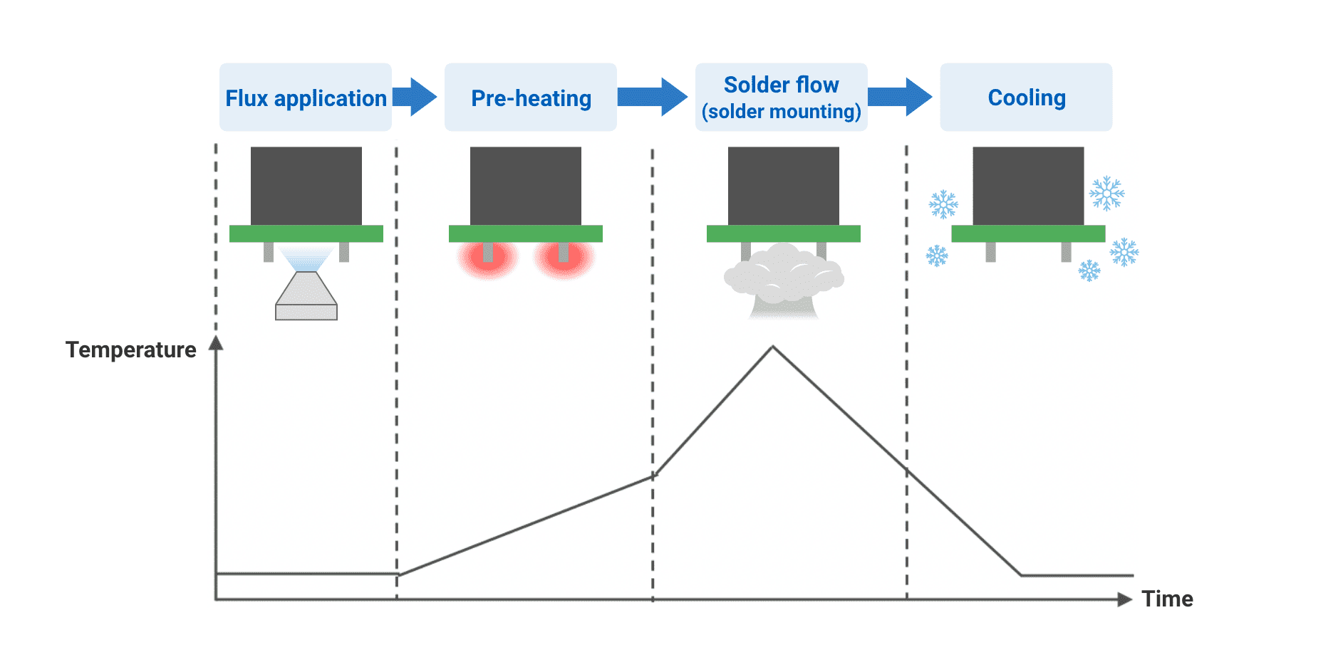
<Image of flow soldering process and temperature change>
Below is the measured temperature profile of OMRON’s main large-current energized relay when solder-mounted. PCBs described in the previous section are used.
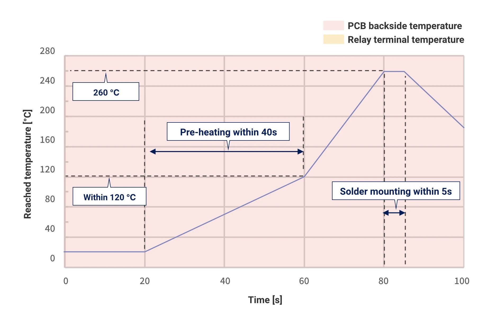
Recommended profile for flow-soldering
Target models: G9KC-4A1B
Compared to the G9KA-1A-E, G9KA-1A, G9KB-1A, and G7EB-1A-E,the terminal size is smaller, making it possible to mount the device under standard mounting conditions.

| Pre-heating section | Backside of PCB |
|---|---|
| Solder mounting section | Relay terminal (unsoldered section) |
| Temperature in pre-heating bath | Approx. 340°C |
| Temperature in solder bath | Approx. 260°C |

| Flux | Solder (lead free) | |
|---|---|---|
| Manufacturer | Tamura Corporation | Senju Metal Industry Co., Ltd. |
| Model | CF-111V-3 | M705 |
Note: These profile conditions are only based on our own evaluations. They do not guarantee the solder mounting conditions, etc.
Please determine your mounting conditions (profile) only after your own evaluation.
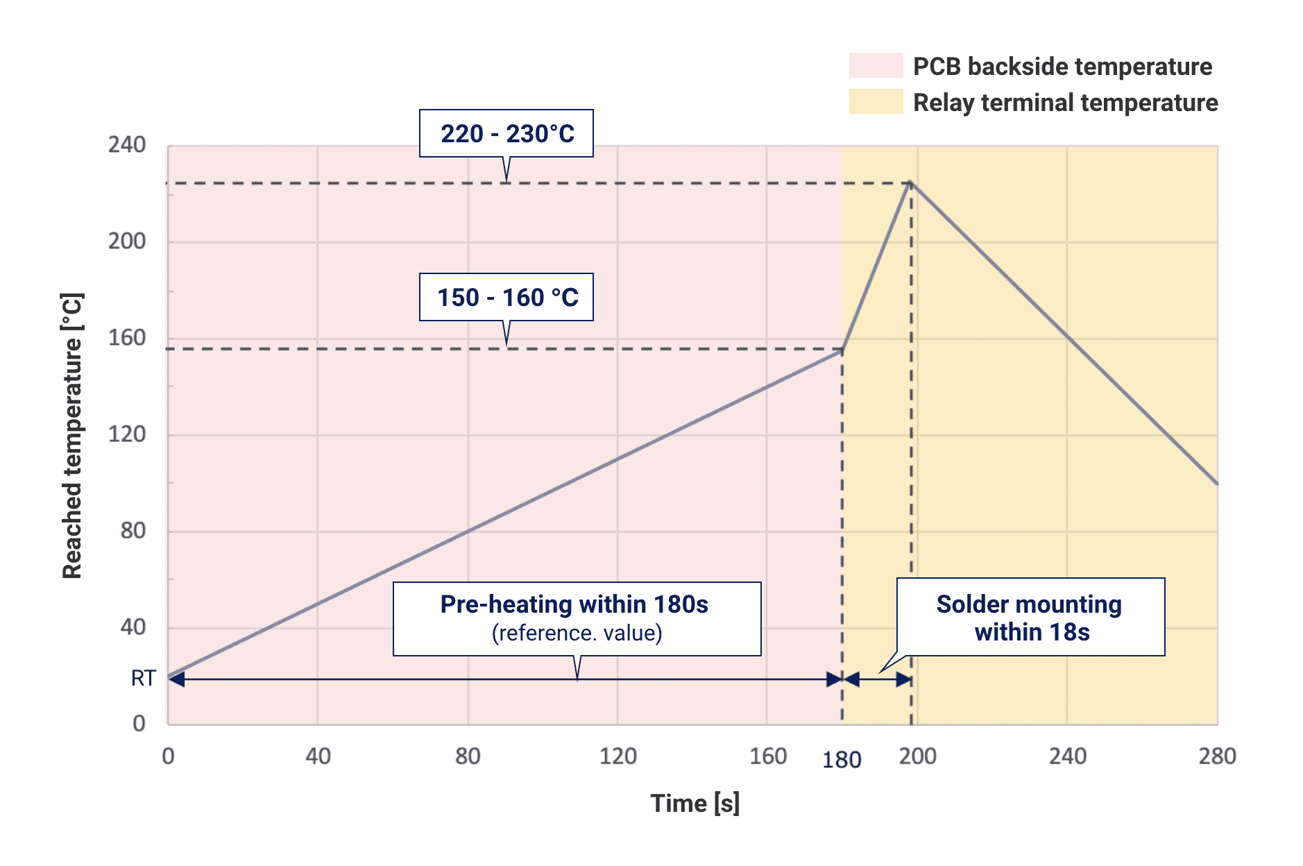
Recommended profile for flow-soldering
Target models: G9KA-1A (-E), G9KB, G7EB-1A (-E)
| Pre-heating section | Backside of PCB |
|---|---|
| Solder mounting section | Relay terminal (unsoldered section) |
| Temperature in pre-heating bath | Approx. 340°C |
| Temperature in solder bath | Approx. 260°C |
| Flux | Solder (lead free) | |
|---|---|---|
| Manufacturer | Tamura Corporation | Senju Metal Industry Co., Ltd. |
| Model | CF-111V-3 | M705 |
Note: These profile conditions are only based on our own evaluations. They do not guarantee the solder mounting conditions, etc.
Please determine your mounting conditions (profile) only after your own evaluation.
It is important to sufficiently heat the PCB and the terminals in the pre-heating section. Increasing the PCB temperature to 150 to 160°C will definitely improve the wettability of the solder.
To improve the wettability of the solder to the relay terminal, the terminal temperature needs to be quickly raised to 220 to 230°C. Adjust the solder bath configuration by referring not only to the temperature but also to the reaching speed.

OMRON's PCB Power Relays
Have you resolved some of your technical concerns about high-capacity power relays? We are sure there are many other concerns.
Please leave your relay-related concerns to OMRON's technical members.
Please contact us first with any concerns you may have.
Power relay FAQ
For other basic questions regarding power relays, please see our FAQ page.
Please use this as well.
Click here for power relay FAQ