vol.278 March 2024


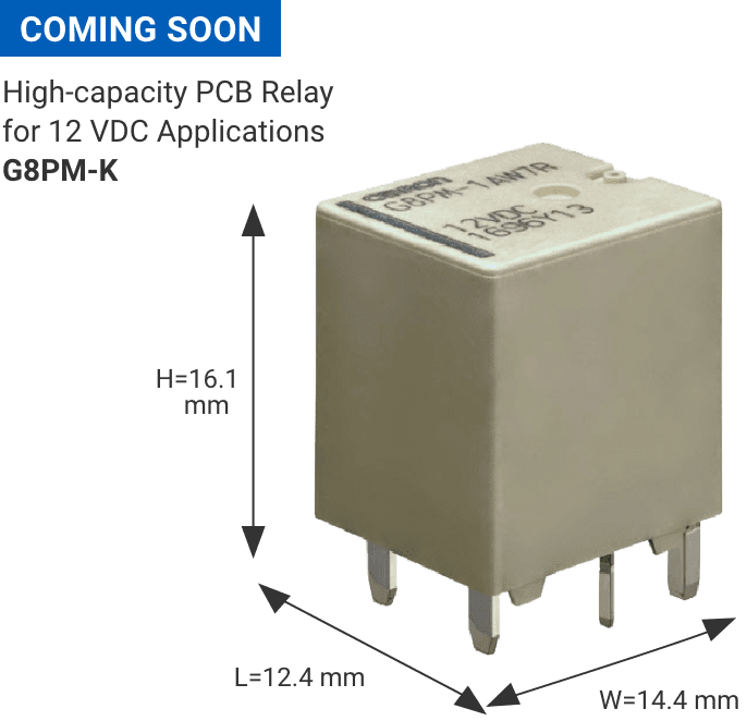
Latching type added to high-capacity PCB relay G8PM suitable for controlling motors, resistors, and lamps in mobility products
- Compatible with through-hole reflow
- Designed for use even at 125°C
- High quality control (TS16949 certified)
Application examples
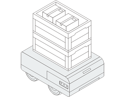
Large AMR
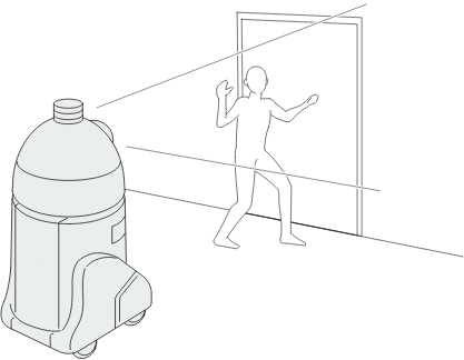
Self-propelled robot
Specifications
| Model | G8PM-K1A71R (positive coil polarity type) G8PM-K1A7R (reverse coil polarity type) |
|
| Rated continuous energizing current | 20°C | 40 A |
| 125°C | 20 A | |
| Maximum switching current | 100 A inrush, 40 A cutoff *1 | |
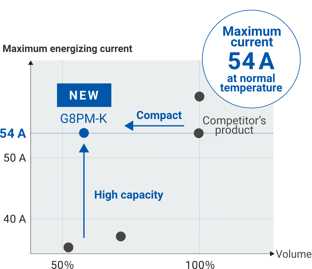
| Maximum energizing current *2 | 135% fuse rating | For 1 hour at 54 A, 14 VDC |
| 200% fuse rating | For 2 minutes at 81 A, 14 VDC | |
| Minimum switching current | 12 VDC, 1 A | |
*1. 100 switching times with a resistive load at normal temperature. Coil voltage is 14 VDC.
*2. Maximum energizing current is the allowable energizing current in abnormal situations, and is not a value that guarantees repeated energization.
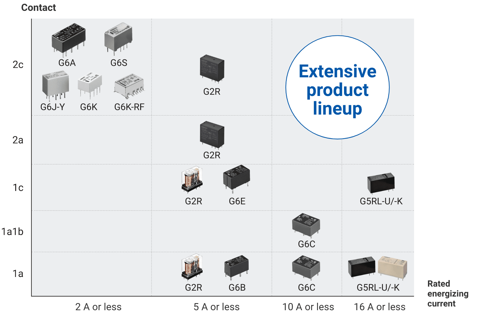
PCB Latching Relays
PCB latching relay lineup
Application examples

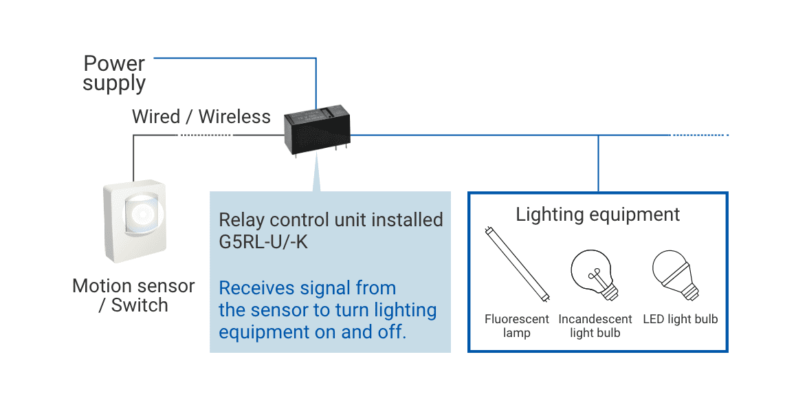
Lighting equipment

Smart tap
Smart meter
Uninterruptible power supply

PV inverter
System configuration example (lighting equipment)
* Contents as of February 2024.
In the interest of product improvement, specifications are subject to change without notice