Definition
Solid state relays (SSRs), unlike mechanical relays, are defined to switch load by carrying signals in electronic circuits.
※These are also called non-contact relays and semiconductor relays.
Solid State Relay Features
Unlike contact relays, these relays do not have a mechanical drive unit, but are composed of electronic components such as semiconductors.
Unlike contact relays, these relays do not have a mechanical operating unit, but are composed of electronic components such as semiconductors.
As for features of Omron’s solid-state relays (SSRs), we have wide range of products, such as integrated with heat sink type, separate with heat sink type, and the same types with plug-in relay, that are compatible with the types of loads and the customer's use environment (installation method and space restrictions) .
Solid State Relay Types
| Types | Loading current | Points |
|---|---|---|
| SSRs integrated with heat sinks | ~150A | The integrated heat sink enables a slim design. These relays are mainly installed in control panels. |
| SSRs with separate heat sinks | ~90A | Separate installation of heat sinks allows the customers to select heat sinks to match the housings of the devices they use. These relays are mainly built into the devices. |
| SSRs of same shape with the relay | ~3A (~10A: Hybrid relay) |
These relays have the same shape as plug-in relays and the same sockets can be used. They are usually built into control panels and used for I/O applications for programmable controllers and other devices. |
| PCB-mounted SSRs | ~3A | SSRs with terminal structure for mounting to PCBs. |
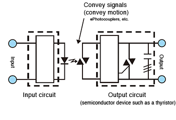
Solid State Relay Diagram
SSR structure (image)
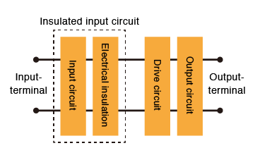
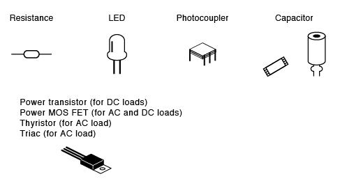
Structural parts of SSR (Examples)

The input device (switch) is turned ON.
Current flows to the input circuits, the photocoupler operates, and an electric signal is transferred to the trigger circuit in the output circuits.
The switching element in the output circuit turns ON.
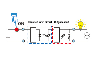
When the switching element turns ON, load current flows and the lamp turns ON.

The input device (switch) is turned OFF.
When the photocoupler turns OFF, the trigger circuit in the output circuits turns OFF, which turns OFF the switching element.
When the switching element turns OFF, the lamp turns OFF.
Solid State Relay Application Examples
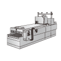
Furnaces (e.g., Baking furnaces)
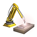
Robots
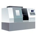
Machine tools
Molding machines
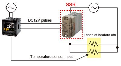
Basic Structure (Case of temperature control)
The SSR receives voltage pulses (such as DC12V) from a temperature controller to turn on/off the load circuits.
To select a product, information of the input voltage and input current of SSR is required.