What is the insulation resistance of a basic switch?
ID: FAQE20019E
update:
Answer
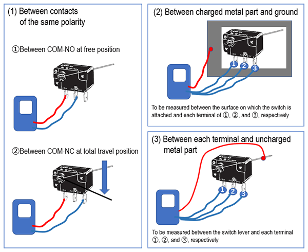
The insulation resistance of a basic switch indicates the resistance (1) between the same polarity terminals, (2) between the charged metal part and ground, and (3) between each terminal and the uncharged metal part.
Explanation
The insulation resistance is measured with an insulation resistance meter (Megger) between the following: two points of the same polarity terminals between COM-NO in the FP state and between COM-NC in the TTP state (in the case of the c-contact specification).
For more information, please see "Switch Basics" Technology / Electrical Characteristics.
Quick tips
No Tips
| Product category | Switches Basic Switches |
|---|---|
| Classification | Selection, Characteristics |
| Related keywords |
|