Photomicrosensor Basics: Precautions
- Basics
- Terminology
- Design
- Precautions
The following provides the instructions required for the operation of Photomicrosensors (photointerrupters).
Transmissive Photomicrosensor (Phototransistor Output Type)
When using a transmissive Photomicrosensor (photointerrupter) to sense the following objects, make sure that the Photomicrosensor operates properly.
- Optically transmissive objects such as paper, film, and plastic
- Objects smaller than the size of the apertures of the Photomicrosensor.
The above objects do not fully intercept the optical beam emitted by the LED. Therefore, some part of the optical beam, which is considered noise, reaches the phototransistor and a light current flows.
Before sensing such type of objects, it is necessary to measure the light currents with and without an object to make sure that the circuit design can sense objects without noise interference from the light that isn’t blocked.
If the light current of the Photomicrosensor sensing any one of the objects is IL(N) and that of the Photomicrosensor sensing none of the objects is IL(S), the signal-noise ratio (S/N ratio) is obtained from the following:
S / N = IL(S) / IL(N)
In consideration with the light current (IL) varies mainly with the aging change by LED degradation and ambient temperature, if the S/N ratio is 4 times or less, it is necessary to pay utmost attention to the circuit of the Photomicrosensor.
Figure 23. Sensitivity Adjustment
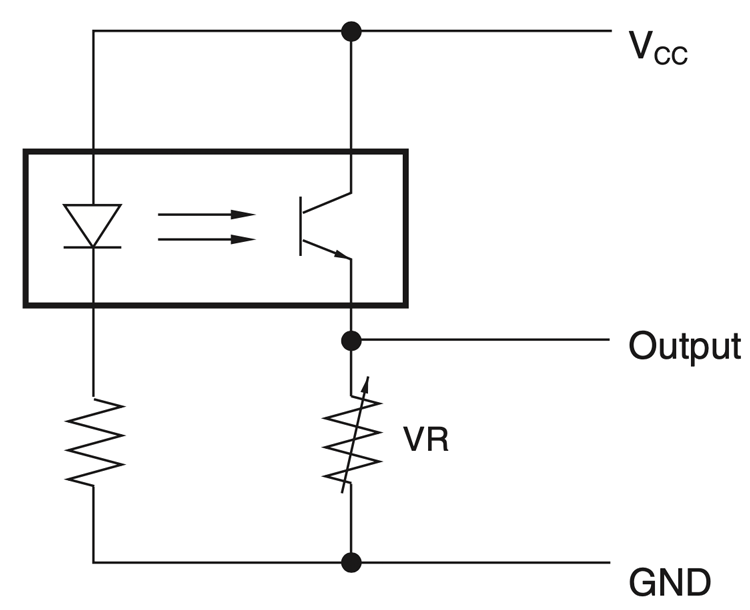
The IL of Photomicrosensors (photointerrupters) varies from piece to piece. According to the datasheet of EE-SX1081, for example, the IL ranges from 0.5 mA to 14 mA (28 times). Each Photomicrosensor has a possibility of having a single, specific value that falls within that range. That value can be at the low end, while the value for another Photomicrosensor with the same part number can be at the high end. Therefore, when multiple Photomicrosensors are used, a variable resistor must be used to accommodate each Photomicrosensor as shown in Figure 23, if the light currents of the Photomicrosensors greatly differ from one another based on production lot.
Figure 24. Aperture Example
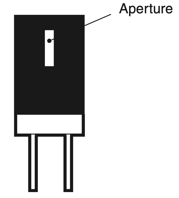
Detecting objects smaller than the aperture size also generates noise, which also reduces the S/N ratio. Photomicrosensors (photointerrupters) having narrow apertures can improve the S/N ratio. However, special attention should be paid to the fact that the light current (IL) will decrease with narrow apertures. This is because less light from the LED is incident on the base of the photosensitive portion of the detector element, as the aperture becomes smaller.
Figure 25. Chattering Output Signal
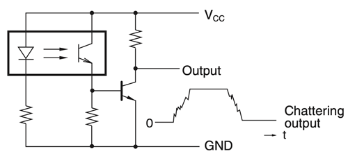
When using the transmissive Photomicrosensor (photointerrupter) with a phototransistor output to sense any object that moves with vibration, moves very slowly, or has highly reflective edges, the Photomicrosensor may have a chattering output signal as shown in Figure 25. If this signal is input to a counter, the counter will have a counting error or operate improperly.
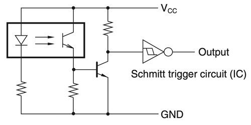
To prevent the chattering problem, add a 0.01- to 0.02-µF capacitor (C) to the circuit as shown in Figure 26 or connect a Schmitt trigger circuit to the circuit as shown in Figure 27.
Figure 26. Chattering Prevention (1)
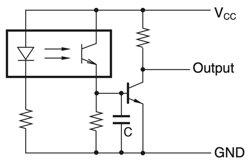
Figure 27. Chattering Prevention (2)
Reflective Photomicrosensor (Phototransistor Output Type)
When using a reflective Photomicrosensor to sense objects, pay attention to the following so that the Photomicrosensor operates properly:
- External light interference
- Background conditions
- Light current change against objects
The typical structure of a reflective Photomicrosensor is shown in Figure 28. The detector element faces to the outside so that it is easily influenced by external light interference. Some of our reflective Photomicrosensors have a filter that intercepts any light, the wavelength of which is shorter than a certain wavelength, to prevent external light interference. Refer to Figure 29 for the light interception characteristics of filters. However, the filter does not perfectly avoid the external light interference. Therefore, the reflective Photomicrosensor must be physically located with minimal external light as much as possible, otherwise the S/N ratio considerably decreases.
Figure 29. Light interception Characteristics of Filters
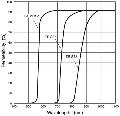
Figure 28. Configuration of Reflective Photomicrosensor
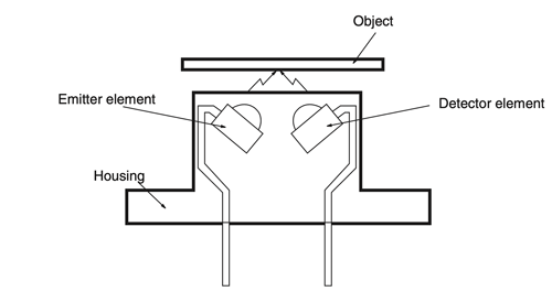
Figure 30. Influence of Background object
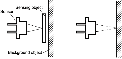
Unlike the output (i.e., IL) of any transmissive Photomicrosensor, the light current (IL) of a reflective Photomicrosensor greatly varies according to type of sensed object, sensing distance, size of the sensed object and the presence of background surfaces (located behind the sensed object).
Some issues that arise when using reflective Photomicrosensors are caused by background objects or surfaces located behind the sensed objects. With regards to the background conditions, the following description assumes that there is no external light present.
Figure 30 shows that the optical beam emitted from the LED is reflected by a sensed object and by the background object. The optical beam reflected by the background object is considered noise that eventually lowers the signal-noise ratio (S/N ratio). Consider a reflective stainless steel or zinc-plated background surface located behind an object to be sensed, such as a piece of paper.
Figure 31. Example of Countermeasure
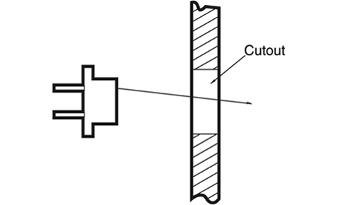
In that case, the light current (IL(N)) produced when sensing the background may be larger than the light current (IL(S)) when sensing the paper.
Making a hole larger than the sensing spot size in the background surface is one of the solutions that can improve the S/N ratio (see Figure 31). Other solutions include:
- Applying a black lusterless paint to the surface of the background, to eliminate or reduce its reflectivity.
- Roughening the surface of the background, achieving a matte finish that will diffuse the reflected light.
- Install the reflective Photomicrosensor so that the LED’s beam will be positioned at an angle to the background surface.
The light current (IL) of the transmissive Photomicrosensor (photointerrupter) is output when there is no sensing object in its slot. On the other hand, the light current (IL) of the reflective Photomicrosensor is output when there is a specified standard object with the specified sensing distance by Omron.
For example, the standard sensing object of EE-SF5-B is white paper having 90% reflectance and the sensing distance is specified as d=5 mm.
In an actual operation, the light current (IL) of EE-SF5-B varies by the types of the actual sensing object, the actual sensing distance, and the other sensing conditions. Figure 32 shows, for example, how the IL of the EE-SF5-B varies according to varieties of sensing objects with sensing distances. Before using the EE-SF5-B, it is necessary to investigate the relationship (ratio) between the IL for the specified standard object and the IL for the actual sensing object by measuring both the IL. Then the range of the IL with the EE-SF5-B in the actual operation can be predicted.
Electrical and Optical Characteristics (Ta = 25°C)
| Item | Symbol | Value | Unit | Condition | |||
|---|---|---|---|---|---|---|---|
| MIN. | TYP. | MAX. | |||||
| Emitter | Forward voltage | VF | - | 1.2 | 1.5 | V | IF = 30 mA |
| Reverse current | VR | - | 0.01 | 10 | μA | VR = 4 V | |
| Peak emission wavelength | λP | - | 940 | - | nm | IF = 20 mA | |
| Detector | Light current | IL | 200 | - | 2000 | μA | IF = 20 mA, VCE = 10 V Reflectance 90% White paper d = 5 mm* |
| Dark current | ID | - | 2 | 200 | nA | VCE = 10 V, 0 ℓx |
|
| Leakage current | ILEAK | - | - | 2 | μA | F = 20 mA, VCE = 10 V Non-reflective state |
|
| Collector-Emitter saturated voltage |
VCE (sat) |
- | - | - | V | - | |
| Peak spectral sensitivity wavelength |
λP | - | 850 | - | nm | VCE = 10 V | |
| Rising time | tr | - | 30 | - | μs | VCC = 5 V, RL = 1 kΩ IL = 1 mA |
|
| Falling time | tf | - | 30 | - | μs | VCC = 5 V, RL = 1 kΩ IL = 1 mA |
|
* “d” is the distance from the top of the sensor to the reflective surface
Figure 32. Sensing Distance Characteristics
EE-SF5(-B)
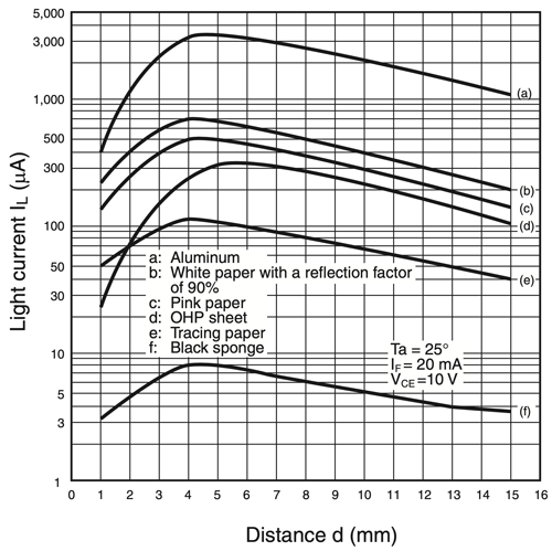
Figure 33 shows the test circuit to measure the IL for both the actual conditions and the specified conditions in the datasheet.
Figure 33. Light Current Measurement
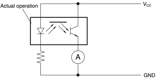
- Prepare some of the Photomicrosensor samples.
- Measure the IL with the specified conditions in the datasheet for each sample.
*The IL range of the Photomicrosensor is specified in the datasheet. - Measure the IL with the actual object for each sample.
- Compare the above IL values. And investigate the relationship(ratio) between the two of the IL.
- Predict the IL range in the actual operation.
- Measure the IL without the object for each sample.
- Calculate the S/N ratio.
After measuring the light currents (IL) with the object and without the object, calculate the signal-noise ratio (S/N ratio) of the actual operation and evaluate if the sensing objects can be sensed stably with the consideration of the IL range and the actual worst-case IL for the actual IF used in the application. The IL of the reflective Photomicrosensor is, however, several tens to hundreds of microamperes. This means that the absolute signal levels of the reflective Photomicrosensor are low. Even if the reflective Photomicrosensor in operation is not interfered by external light, the dark current and the additional current (ID + ILEAK +α) , which are considered noise, may amount to several to ten-odd microamperes due to a rise in the ambient temperature. This noise cannot be ignored.
As a result, the S/N ratio of the reflective Photomicrosensor will be extremely low if any objects with a low reflectance are sensed. Additionally pay utmost attention when applying the reflective Photomicrosensor to the sensing of the following:
- Marked objects (e.g., white objects with a black mark each)
- Minute objects
It is very important to investigate the S/N ratio for the actual sensing operation with the consideration of the worst-case conditions, especially for the reflective Photomicrosensors. If the S/N ratio
is predicted to be small, the special circuit such as an automatic threshold level setting is one of the ways to solve it for a long time and stable sensing.
- Basics
- Terminology
- Design
- Precautions
Click here for the photomicrosensor product lineup