
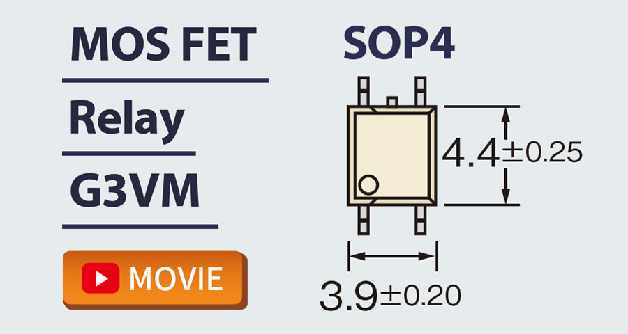
G3VM-61HR/61HR1/61HR2 MOS FET Relays SOP 6-pin, High-current and Low-ON-resistance Type
MOS FET Relays in SOP 6-pin
packages that achieve the low ON
resistance and high switching capacitance
of a mechanical relay
- Load voltage: 60 V
- 60-V Relay (61HR): Continuous load current of 2.3 A (4.6 A) max. *
- 60-V Relay (61HR1): Continuous load current of 3.3 A (6.6 A) max. *
- 60-V Relay (61HR2): Continuous load current of 4 A (8 A) max. *
* Values in parentheses are for connection C.
- Downloadable data
- CAD


DOWNLOAD
This web page provides an excerpt from a datasheet. Refer to Product Datasheet and other applicable documents for more information. You can download CAD data from the "Model list".
Catalog
| Data type | File name | Date of update |
|---|---|---|
| Data sheet | Data sheet G3VM-61HR/61HR1/61HR2 | |
| Precautions | Common Precautions for All MOS FET Relays | |
| Selection Guide | G3VM MOS FET RELAYS SELECTION GUIDE | |
| Technical information | The SOLUTIONS [MOS FET Relay] Membership Only |
MODEL LIST
Relevant information for each model is listed. CAD data can be downloaded after logging in or registering as a member.
| Model | 2D/3D CAD*1 | ECAD*2 | Buy online | RoHS Certification | Product Discontinuation |
|---|---|---|---|---|---|
| G3VM-61HR | Login/Register | Login/Register | RoHS Certificate | In production | |
| G3VM-61HR(TR) | RoHS Certificate | In production | |||
| G3VM-61HR1 | Login/Register | Login/Register | RoHS Certificate | In production | |
| G3VM-61HR1(TR05) | RoHS Certificate | In production | |||
| G3VM-61HR2 | Login/Register | Login/Register | RoHS Certificate | In production | |
| G3VM-61HR2(TR05) | RoHS Certificate | In production |
- *1See here for 2D,3D CAD data specifications.
- *2External site (Ultra Librarian) opens in a new window.
Ultra Librarian uniquely created ECAD data based on the information provided by OMRON. Please note that OMRON does not guarantee the accuracy, concurrence or completeness of ECAD data.