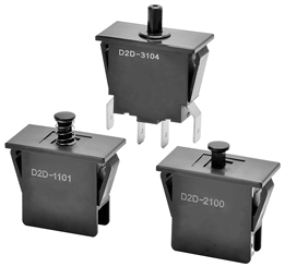
D2D Power/Door Switch
Door Interlock Power Switch with Minimum Contact Gap of 3 mm
- Offers the minimum contact gap of 3 mm required for power switches as standard equipment.
- Safety considerations include a double return spring and direct drive positive contact opening feature.
- Pull-on lock model for easy maintenance is also available.

Mounting method |
Contact form | Standard | Pull-on lock (see note ) |
---|---|---|---|
Contact gap: 3 mm min. | Contact gap: 1 mm | ||
Screw mounting
|
SPDB-NO/NC
|
D2D-1000 | D2D-2000 |
SPDB-NO
|
D2D-1001 | - | |
SPDB-NC
|
D2D-1002 | - | |
Panel mounting
|
SPDB-NO/NC
|
D2D-1100 | D2D-2100 |
SPDB-NO
|
D2D-1101 | - | |
SPDB-NC
|
D2D-1102 | - | |
SPDB-NO+SPDB-NO/NC
|
D2D-3103 | - | |
DPDB-NO
|
D2D-3104 | - |
Contact Form
SPDB-NO/NC | SPDB-NO | SPDB-NC |
SPDB-NO+SPDB-NO/NC | DPDB-NO | |
Type |
|
Resistive load | |||
---|---|---|---|---|---|
Standard
|
250 VAC
|
16A | |||
Pull-on lock
|
250 VAC
|
10A |
Note: | The ratings values apply under the following test conditions: |
Ambient temperature: 20±2ºC | |
Ambient humidity: 65±5% | |
Operating frequency: 30 operations/min |
Characteristics
Item | D2D-1000 models |
D2D-2000 models |
D2D-3000 models |
|||||
---|---|---|---|---|---|---|---|---|
Permissible operating speed
|
10 mm to 1 m/s | |||||||
Permissible
operating frequency |
|
|||||||
Insulation resistance
|
100 MΩ min. (at 500 VDC) | |||||||
Contact resistance
(initial value) |
50 mΩ max. | |||||||
Dielectric
strength (50/60Hz 1min) |
Between terminals
of same polarity |
2,000 VAC | 1,000 VAC | 2,000 VAC | ||||
Between terminals
and ground (see note2) |
2,000 VAC | 1,500 VAC | 2,000 VAC | |||||
Between terminals
and non-current-carrying metal part |
2,500 VAC | 1,500 VAC | - | |||||
Between terminals
and actuator |
4,000 VAC | - | 4,000 VAC | |||||
Vibration resistance
|
Malfunction: 10 to 55 Hz, 1.5-mm double amplitude | |||||||
Shock resistance
|
Destruction: 1,000m/s2 {approx. 100G} max. | |||||||
Malfunction: 500 m/s2 {approx. 50G} max. |
Malfunction: 300 m/s2 {approx. 30G} max. |
Malfunction: 500 m/s2 {approx. 50G} max. |
||||||
Durability *
|
|
|||||||
Degree of protection
|
IEC IP40 | |||||||
Degree of protection
against electric shock |
Class II | |||||||
Proof tracking index (PTI)
|
175 | |||||||
Ambient Operating temperature
|
-25ºC to 85ºC (at ambient humidity of 60% max.) (with no icing or condensation) |
|||||||
Ambient Operating humidity
|
85% max. (for 5 ºC to 35ºC) | |||||||
Weight
|
Approx. 14 g (D2D-1000) |
Note: | The data given above are initial values. | |
* | For testing conditions, consult your OMRON sales representative. |
|
||||||||||||||||||||||||||||||||||||||||||||||||||||
|
||||||||||||||||||||||||||||||||||||||||||||||||||||
|
||||||||||||||||||||||||||||||||||||||||||||||||||||
|
||||||||||||||||||||||||||||||||||||||||||||||||||||
|
||||||||||||||||||||||||||||||||||||||||||||||||||||
|
||||||||||||||||||||||||||||||||||||||||||||||||||||
|
||||||||||||||||||||||||||||||||||||||||||||||||||||
|
||||||||||||||||||||||||||||||||||||||||||||||||||||
|
||||||||||||||||||||||||||||||||||||||||||||||||||||
|
Correct Use
●Mounting
Apply operation force to the pin plunger in the direction it oper- ates. Applying forces laterally or from an oblique direction may damage the pin plunger.
Use M4 mounting screws with plane washers or spring washers to securely mount the Switch. Tighten the screws to a torque of 0.49 to 0.69 Nm {5 to 7 kgcm}
●Wiring
It is recommended to use sleeve receptacles when connecting with the quick connect terminals.
Insert the receptacle straight toward the terminal.
Applying excessive external force horizontally or vertically may cause deformation of terminals and may damage the housings.
●Using Micro Loads
Using a model for ordinary loads to open or close the contact of a micro load circuit may result in faulty contact. It is recommended to use the Switch in the operation range shown below. The minimum applicable load is the N-level reference value. This value indicates the malfunction reference level for the reliability level of 60% (λ60).
(JIS C5003)
The equation, λ60=0.5×10⁻⁶/operations, indicates that the estimated malfunction rate is less than 1/ 2,000,000 operations with a reliability level of 60%.