Explain LED input signal and output sampling time for the analog output model of the light convergent reflective type Optical Sensor B5W-LB.
ID: FAQE40042E
update:
Answer
Refer to Explanation below for the recommended LED input signal and the recommended sampling time of this Optical Sensor.
Explanation
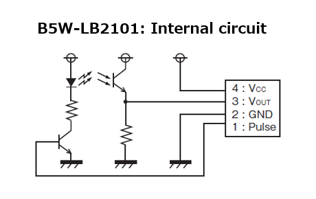
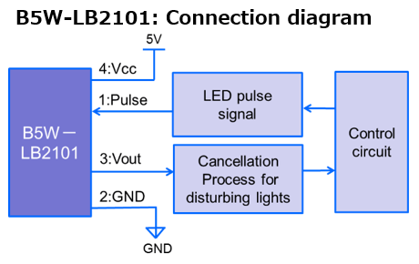
Relatively large current flows through the LED of the B5W-LB series to detect an object with low reflectivity. In order to reduce the load on the LED (for longer life), it must be designed to be pulse-driven rather than DC-driven. The internal circuit and external connection diagrams are shown below.
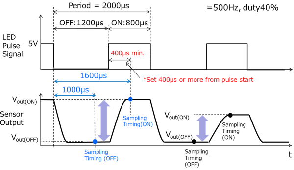
The following figure shows the recommended pulse signal input to the sensor input terminal: 1 and the sampling time of the sensor output. For details, see B5W-LB: User’s Manual.
Quick tips
By designing to be pulse-driven, the effect of external light can be canceled by the external circuit. For details, see B5W-LB: User’s Manual.
| Product category | Sensors Light Convergent Reflective Sensors/Diffuse Reflective Sensors |
|---|---|
| Classification | Usage, Applications |
| Related keywords |
|